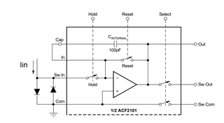
In this Simulation, Why two diodes(D4 1N4148) are connected with current source and also if i simulate without diodes why i am not get simulation result properly.
This thread has been locked.
If you have a related question, please click the "Ask a related question" button in the top right corner. The newly created question will be automatically linked to this question.
Hi Gowtham,
The anti-parallel diodes connected between COM and Sw_In provide a clamp or path for the Iin input current to flow when the Hold switch is opened. When the Hold switch is opened, the input to the ACF2101 becomes high impedance and consequently the Sw_In node will try to go to a large positive voltage. The Hold switch is specified to have a withstand voltage of +0.5V. When the voltage at the Sw In node exceeds +0.5V the Hold switch will begin to conduct again. This will not cause damage to the switch, however, the output will start to unexpectedly integrate again. The addition of the anti-parallel diodes D3 and D4 in the circuit provide a path for the input current to flow and is critical for proper Hold mode operation.
Thank you and Regards,
Luis