This thread has been locked.

If you have a related question, please click the "Ask a related question" button in the top right corner. The newly created question will be automatically linked to this question.

OPA860: Design the OPA860 peak-hold circuit

Part Number: OPA860
Other Parts Discussed in Thread: OPA356

Hi team,

The customer drew the physical board according to the original post, but the actual results of the physical test were still similar to the simulation. Referenced this post:
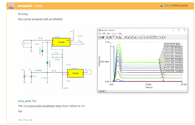
https://e2e.ti.com/support/amplifiers-group/amplifiers/f/amplifiers-forum/1004949/peak-detection-circuit

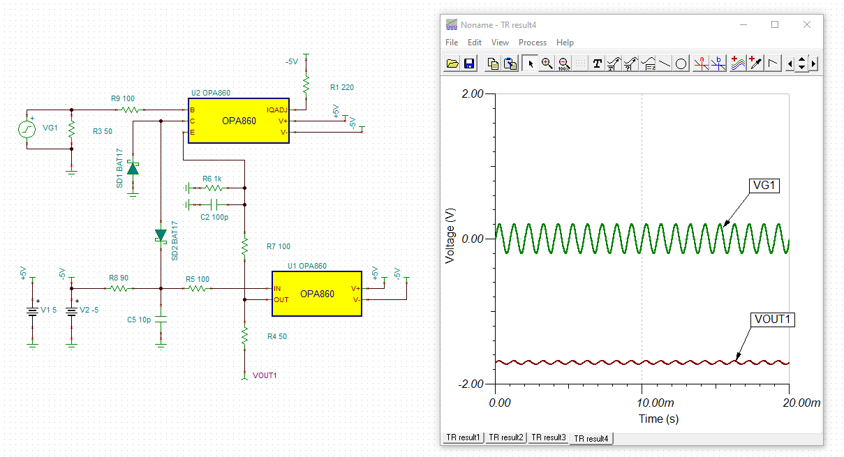
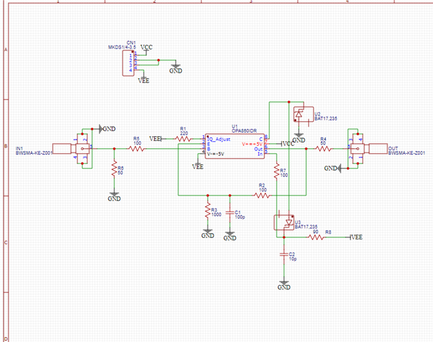
The schematic of the tests performed is as follows: 
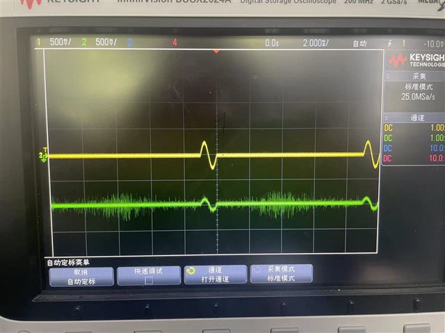
The measured results are as follows: 
Could you help check why's this? Thanks.

Best Regards,

Cherry

  • Hi Cherry,

    the circuit has been optimized to catch 1ns pulses. For much slower input signals, as shown in your scope plot, the circuit would have to be modified. Also, for slower signals there are better suited circuits, like this one, for instance:

    https://e2e.ti.com/support/amplifiers-group/amplifiers/f/amplifiers-forum/1088815/peak-detector-cs0951017

    By the way, R8 = 90R is way too small. In the original schematic  I used a 90M resistor to provide some input bias current cancelling.

    What is your input signal? Can you tell more about your application?

    Kai

  • Hi Kai,

    Thanks for your support.

    The input signal is the yellow end of the scope plot, a 1 kHz burst signal with an amplitude of 500 mV. In fact, this circuit is used to obtain the maximum value of the ultrasound signal for excitation, so the bandwidth requirement is typically 70M upwards. However, the customer wants to test the 1kHz signal first and then try with a 20M or higher pulse parameter.

    But why is the effect of a follower?

    Thanks and regards,

    Cherry

  • Hi Cherry,

    But why is the effect of a follower?

    This happens when R8 = 90R instead of R8 = 90M and R8 shortcircuits C5 regarding HF:

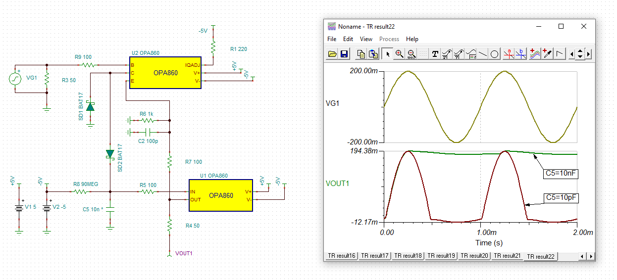
    cherry_opa860.TSC

    Because of R8 = 90R the cathode of SD2 and pin "C" of OPA860 are forced to negative potentials. This has the consequence that SD2 is permanently turned-on. The input signal at pin "B" modulates the negative potential at pin "C" and by this the current through SD2. This results in a big negative DC output voltage being superimposed by a small copy of the input signal. This looks like a voltage follower performance sitting on a big negative DC offset.

    But even if R8 = 90M or higher, C5 cannot hold the positive peak of 1kHz signal, because C5 = 10p and its stored charge is way too small to be able to keep the voltage as soon as the 1kHz signal moves from the positive peak back down to smaller voltages. The leakage current through R8 and the "IN" pin immedialy reload C5 and does not allow it to fully store the charge until the next positve peak of 1kHz signal arrives. You would need to considerably increase C5 to make this peak detector properly work down to 1kHz signals. C5 should be increased to about 10n or more:

    Kai

  • Hi Kai,

    The customer is trying to set R8 to a 10M resistor, causing the input signal (which is sent by the function generator at 10M frequency and 1V amplitude) to change from a normal pulse input to a redundant signal.

    If the peak value of a pulse signal above 10M needs to be sampled, is there anything else to change the value of C5 capacitor besides changing the value of R8?

    Thanks and Regards,

    Cherry

  • Hi Cherry,

    I would increase C5 to 10nF.

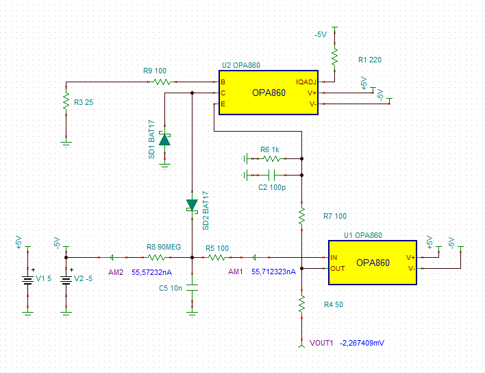
    R8 is necessary to compensate the input bias current of buffer, In order to allow an almost zero output voltage with no input signal. 

    Since the input bias current of buffer can vary between -7µA and +7µA from chip to chip, R8 needs to be optimized for each chip by trial and error. This may also mean that R8 has to be connected to +5V instead of -5V. In the simulation above setting R8 = 90M and connecting it to -5V was a good choice. But in your circuit you may need something different.

    Again, this originally is a circuit to catch 1ns pulses and the OPA860 was used because it is ultra fast. Unfortunately, the OPA860 is not ultra precise. If you need something that is more precise and does not need an input bias current cancellation, then see the link above. Because of ultra low input bias currents you may profit from a CMOS- or FET-OPAmp then. The OPA356 may be a good candidate.

    Kai