


Part Number: OPA860
Other Parts Discussed in Thread: OPA861
Hello,
I designed a peak hold circuit using OPA860 and OPA861, a transistor amplifier chip, where the physical design and simulation design principles are similar. However, without its built-in buffer, the input and output signals are perfectly aligned to form a follower.
In the physical design, the circuit designed with OPA860 is designed according to the successful simulation circuit principle, and the output signal is still the same as the input signal to form the follower function, and the experimental result of OPA861 is the same. Thank you very much!
Below is the circuit and curve disabled buffer, it could be found that it is one follower.
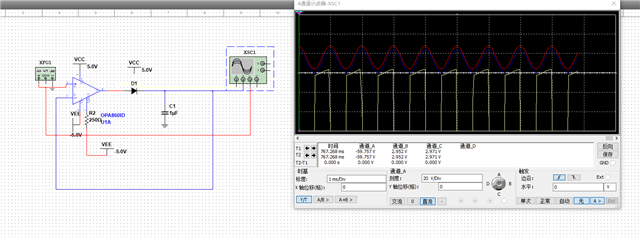
If enable the buffer, it is peak detection circuit .
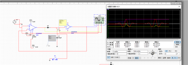
So the question is that why it is follower when disabled buffer, while enable buffer, it could realize peak detection circuit.
Best regards
Kailyn

