A related question is a question created from another question. When the related question is created, it will be automatically linked to the original question.
If you have a related question, please click the "Ask a related question" button in the top right corner. The newly created question will be automatically linked to this question.
The typical short-circuit current is 12 mA, so your current should be much lower than that.
The curve at the bottom of p. 4 does not go beyond 4 mA. The first paragraph on p. 6 says that you should not go above 3.7 mA if you want to be able to reach the minimum loop current of 4 mA.
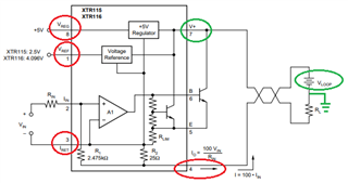
Please follow Clements suggestions. XTR115/XTR116/XTR117 are all part of 2-wire 4-20mA current loop transmitters, where the input signals are required to "float" and referenced to IRet pins only in a design.
Only one true GND node is allowed in the 2-wire, 4-20mA current loop transmitter architecture, typically the GND is allocated at the Vloop or Vsupply power source side (floating Vloop supply will cost more). All other onboard voltage references and input signals are referenced to pin3 or Iret node. The sum of all current branches within the loop can not exceed 3.7mA at pin4, when the total current exits from the node at Vin = 0V input signals w.r.t. Iret pin. Typically, the Vin is configured from 0V to 5V (w.r.t. Iret), the output current is converted from Vin (DC or AC) --> 4mA to 20mA (DC or AC signal) which are linearly proportional of the V-to-I converter.
The link below has tons of reference designs, videos and how to work with the similar products. If you have additional questions, please let us know.