This thread has been locked.

If you have a related question, please click the "Ask a related question" button in the top right corner. The newly created question will be automatically linked to this question.

INA238: Over-large measurement error of INA238 compared with datasheet

Part Number: INA238
Other Parts Discussed in Thread: INA236, INA226

Question in brief:

Hi, My customer wants to use INA238 to replace INA236 to measure the current.

Datasheets shows that INA238 has the same measurement accuracy as INA236.

(5uV offset, 0.1% gain error,16 bits ADC…)

However, customer’s testing data shows that the measurement errors of INA238 exceed the nominal value of the datasheet, while the measurement errors of INA236 is within the normal level.

The customer wants to figure out why the test results cannot coincide with the datasheet, and what other factors will influence the measurement accuracy of INA238?

Detailed test conditions and results can be seen in the appendix (attachment):

Question Description of INA238.docx

Many thanks!

  • Hello Matt,

    Thank you for using the TI forum. Can you please have them remove the capacitors to GND on IN+ and IN- (C189, C192, C231, C266), and have them check to see if that fixes the issues. Here is an E2E that discusses why they may not want these caps: https://e2e.ti.com/support/amplifiers-group/amplifiers/f/amplifiers-forum/1221725/ina280-any-issue-if-the-input-common-mode-cap-value-is-mismatched

    Regards,

    Mitch

  • Hi Mitch,

    My customer have removed the capacitors to GND on IN+ and IN-, and the problems have not been solved, and the measurement error enhanced (maybe there is a common mode interference in the instrument).

    Can you analyze what other factors will cause the difference between the measurement results of INA236 and INA238?

    Regards,

    Matt

  • Hello Matt,

    Ok, I have a few more questions for you:

    1. How are you measuring your current reference?  In the document you sent, it looks like you are calculating the error off of the the ideal current value. How do we know that the actual current is not something different, for example half way in between the measured value for both devices?
    2. Can you send the details for your shunt resistor?  It's possible this is introducing more error across temperature. 
    3. How are you measuring the current at 0V? to ensure a more accurate value, make sure that either IN+ or IN- is disconnected, and that there are no leakage currents.
    4. Can you send a full register readout for both devices at the same current level (ex, at 10A), this will help us better analyze the data.

    Regards,

    Mitch 

  • Hi Mitch,

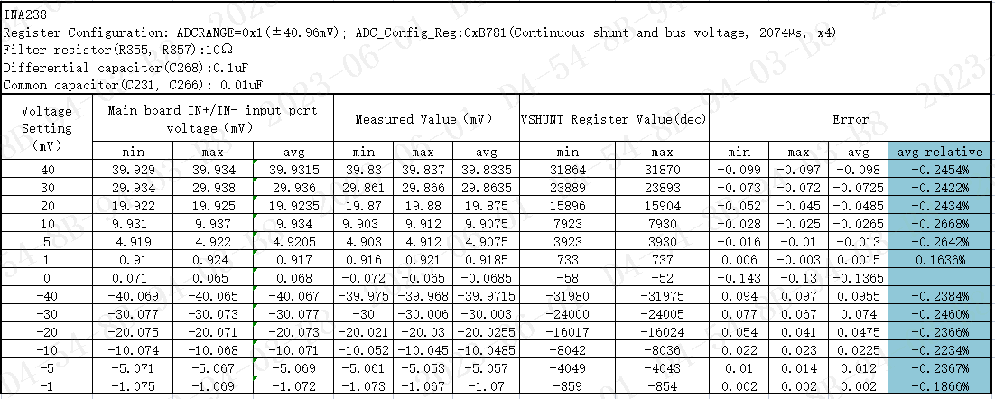
    Customer has received our INA238 EVM and re-test the error, and find it violates the datasheet specification.

    You can find the register configuration and the test results as below, 

    YYou can also see more details in the excel file /cfs-file/__key/communityserver-discussions-components-files/14/INA236-INA238-shunt-current-test--siyuan-0601.xlsx. It shows that INA236 test error is much lower than INA238.

    This issue has been pending for a while, pls kindly help!

    Also, I think you can provide customer how you test the sense error on our EVM and what is the results you have got. Thanks!

    Regards,

    Xiaoying

  • Hello Xiaoying,

    Going over your data and the datasheets, it looks like the error you are seeing is from the common mode voltage.

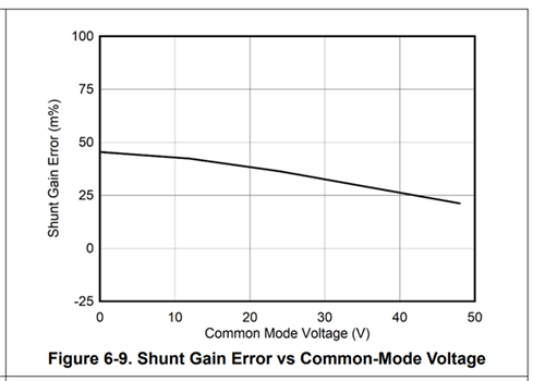
    For the INA236, all of the errors are specified with a common mode of 12V. From Figure 6-9 of the datasheet here is the change in gain error with common mode voltage:

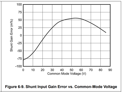
    The error specifications for the INA238 are actually specified at 48V. Here is change in gain error with common mode voltage for this device:

    You can see from the above that if your common mode voltage is low, there will be additional gain error for the INA238 compared to the INA226 at the same common mode voltage.

    In addition, from the data you sent it looks like there is more measurement variation in the multimeter than the device itself. To accurately compare results and analyze the INA device, you’ll want a measurement tool that is more precise than the INA itself. Here are some notes about the measurement you are taking when comparing accuracy:

    For your measurement:

    • Make sure you are probing as close to the device pins as possible.
    • Make sure you are using a precision multimeter for the best results.
    • Consider these settings of the DMM
      • Range
      • Number of power line cycles (NPCs – averages)
      • Input impedance

    Regards,

    Mitch