This thread has been locked.
If you have a related question, please click the "Ask a related question" button in the top right corner. The newly created question will be automatically linked to this question.
Dear Team,
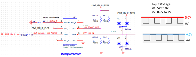
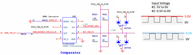
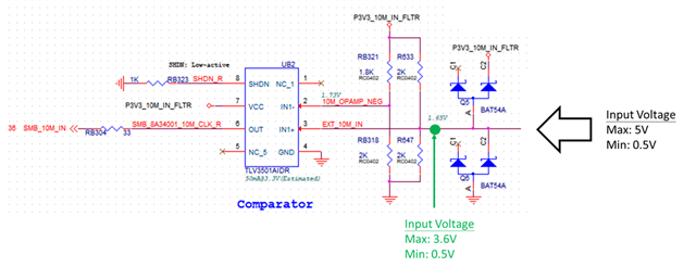
Input voltage swing is from 3.6V to 0.5V, and it could not be recognized by TLV3501A. Please help review and comment hot to improve to make sure UB2 can recognize and output voltage correctly. Thanks.
UB2:
Thanks a lot,
Jimmy
What exactly do you mean with "could not be recognized"? What are the input and output voltages? Can you show an oscilloscope trace?
Hi Jimmy,
In addition to Clemens questions, I would also like to add that 3.6V is right on the abs max rating of the input voltage range. we do not recommend operating right on the abs max. What happens if the max input is divided further to something like 3.3V?
Hi Chi,
Thanks for your great support.
For comparator, it includes two types of input voltage below. I have a couple of questions below
Many Thanks,
Jimmy
Hi Jimmy, we are on holiday break today and will review your post when we are back tomorrow
Hi Chi,
We appreciated your great support.
I’ve understood what the use of hysteresis. Let me update these questions as follow.
Thanks.
Jimmy
Hi Jimmy,
Chi is out until Thursday.
Is the input signal AC coupled?
If you do add hysteresis, there should also be a resistor in series with the input (between input and divider) to create the hysteresis.
Please see the following appnote on hysteresis:
Hi Chi and Paul,
Thanks for your great support!
Typical hysteresis is 6mV and our expected the minimum input swing is 0.225V(0.25V +/-10%). I have no idea if hysteresis is required. Please help advise. Thanks.
Jimmy
Jimmy,
I am not really sure what you are asking for. The typical hysteresis is 6mV which is the internal hysteresis of the device but if you need more, then you need to design for external hysteresis. The process to design for hysteresis is described in the app note Paul referred to. How much of a hysteresis window is dependent on what you or the customer needs. We also have a calculator tool if that helps as well. I also just made an example of a ~350mV hysteresis circuit below.
Hi Chi and Paul,
Thanks for your great support!
Regarding the attached file, it looks for 7752 comparator, is it also available for TLV3501? Thanks.
Please find the attachment.
7752.Comparator Hysteresis Tool 1.xlsx
Many Thanks,
Jimmy
Jimmy,
Sorry must have been a typo, yes this tool works for any push pull/open drain devices.
I noticed you had 50 mV for the internal hysteresis line. That is the internal hysteresis of the device itself (which is 6 mV for TLV3501). The total amount of hysteresis you desire is inputted via the VH and VL line so I would change 50 mV to 6mV. Other than that it looks fine.
Hi Chi,
Thanks for your great support.
Our required hysteresis voltage is 50mV and related resistance can be derived from the TLV3501A datasheet below. It is different from TI’s tool. Even I use the parameters(derived by TI’s tool) into the formula of the TLV3501 datasheet. Hysteresis voltage is still not similar. Please help confirm. Thanks.
R1 = 50-ohm
R2 = 3.42K-ohm
V+ = 3.3V
R1 = 22E-12 ohm
R2 = 10K-ohm
V+ = 3.3V
TLV3501A datasheet
Many Thanks,
Jimmy
Jimmy,
As I have mentioned before, the VHYST_INT line in the calculator is for the internal hysteresis of the device itself (6 mV). You are already accounting for the TOTAL hysteresis by setting the VH and VL lines. 1.675 - 1.625 is 50 mV. The tool will just create an extra 44 mV on top of the 6 mV internal to create the 50mV.
This is what I get from the tools values. Its not super precise but it gets close to the targeted thresholds. You may need to tune it a little if you need it to be more precise.
You could also just use the app note Paul referenced earlier to do the hand calculation your self. You would just design for 44 mV of hysteresis since the 6mV is already inside the chip. Non-inverting comparator with hysteresis circuit (Rev. A)