This thread has been locked.
If you have a related question, please click the "Ask a related question" button in the top right corner. The newly created question will be automatically linked to this question.
Hi team,
We are currently using INA199 for our BMS Current Sense Application.
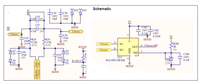
The current sense resistor (0.1 milli ohm) is placed on the negative line ( between the overall pack negative and cell 0). Using a kelvin 4 connection, we are sensing the shunt current using INA199C, whose output is going to the microcontroller's ADC pin.
During normal application ( Bulk Current, not injected), this setup works absolutely fine. But when a bulk current of around 60 mA ( 20 to 200 MHz) is injected along with a 50 A signal, the output is totally skewed with upto 100% error.
How can this error be mitigated ? Looking for some tips with respect to layout, Rf and Cf selection etc. Thanks in Advance.
Regards.
Hi Prashaant,
Can you provide a schematic of this system? Do you also have a scope screenshot showing the output with 100% error?
Its possible that the common-mode voltage is dropping below the absolute maximum rating of -0.1V, resulting in significant error.
Cierra
Hi Cierra,
Attached the schematic below.
schematic of this system?
The " CSENSE+ Conn "and " CSENSE- Conn " at the bottom left is coming from a connector, which is connected across a shunt of 0.1 milliohm.
The CSenseADC connected at INA199C3DCKR (200V/V) is going to the microcontroller's ADC and thus calculating the current through ADC value.
scope screenshot
Unfortunately, we do not have the scope screenshot since and we are getting the signal data through the ADC only.
Hi Prashaant,
The error could be the result of mismatch between the capacitors between the input pins and ground. Please see this E2E posts which demonstrates this: https://e2e.ti.com/support/amplifiers-group/amplifiers/f/amplifiers-forum/1221725/ina280-any-issue-if-the-input-common-mode-cap-value-is-mismatched/4612946?tisearch=e2e-sitesearch&keymatch=common%2520mode%2520capacitor#4612946
You will see that even a small mismatch of ~3% between the capacitors can result in significant error. I would recommend removing these capacitors and see if this resolves the issue.
The series resistance on the input pins will also contribute to error. We generally recommend keeping these resistors <10 ohm when using an input filter. Please see INA199 datasheet Section 8.4.1: input filtering.
Cierra
I would recommend removing these capacitors and see if this resolves the issue.
Thanks CIerra. Will try that.
Also is there any standard recommended value for Rs and Cf values that we can go ahead and try.
In addition to that, will placing a 0.1uF capacitor between IN+ and GND, and IN- and GND help us get better results attenuating the common mode noise?
Thanks,
Prashaant
Hi Prashaant,
Also is there any standard recommended value for Rs and Cf values that we can go ahead and try.
Section 8.4.1 of the datasheet recommends Rs < 10 Ω. You can determine Cf from the cutoff frequency equation: f = 1 / (2π * [Rs + Rs ] * Cf )
In addition to that, will placing a 0.1uF capacitor between IN+ and GND, and IN- and GND help us get better results attenuating the common mode noise?
No, you should avoid using a capacitor from IN+ to GND, or IN- to GND. The capacitors would have to be extremely well matched with low tolerance, as mentioned in the E2E discussion linked in my previous reply.
Have you tried without any input filtering at all? I want to verify whether the input filter is necessary. Please try without any input filter or extra components (connect the shunt sense resistor directly to the input pins of the INA199). If you do experience a noisy input signal with this configuration, then try adding the differential RC filter suggested by section 8.4.1.
Please let me know if a noisy input signal persists after that.
Thanks,
Cierra