This thread has been locked.
If you have a related question, please click the "Ask a related question" button in the top right corner. The newly created question will be automatically linked to this question.
Hi,
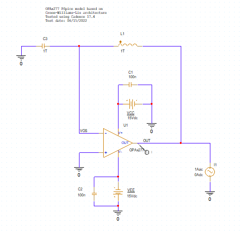
When compare the open impedance of OPA205 and OPA277 with their PSpice models, we find the result from OPA205 agrees with the datasheet well. But the one for OPA277 is about x10 different from the datasheet.
The simulated result is as below:
The one given by datasheet:
Where is wrong?
Thanks.
Hi Diverger,
I performed the AC simulation analysis of the OPA277 Zo -- Open-loop Output Impedance, on both TINA-TI and PSPICE-for-TI.
Both the TINA-TI and PSPICE-for-TI models provide the correct result.
To plot the small-signal open-loop output impedance over frequency, I used the test circuit below. The large inductor and capacitor are used to provide a valid DC bias point, and to simulate the open-loop AC analysis. I apply an AC test current source at the amplifier output, and sense the voltage at the amplifier output. I perform an AC sweep and calculate the open-loop output impedance as V(OUT) / I(U1:OUT). The Y-axis is set to the Log scale to match the datasheet plot.
Thank you and Regards,
Luis
Sorry, I made a mistake that the plot is actually of OPA205A. So both of them agree with the datasheet.
HI Diverger,
Thank you very much for the update, glad that both work and agree with the datasheet,
Kind Regards,
Luis