This thread has been locked.

If you have a related question, please click the "Ask a related question" button in the top right corner. The newly created question will be automatically linked to this question.

INA849: Excessive Output Noise

Part Number: INA849
Other Parts Discussed in Thread: OPA1662, , INA851, INA163, INA166

Hi,

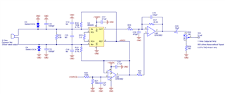
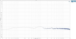
I am having problems with an INA849 amplifier circuit. The input is intended to interface to an un-amplified dynamic 5 Ohm microphone with a 250uVrms output. For the purpose of measuring the performance of the amplifier I'm using an Audio Precision generator with a 40 Ohm balanced output. The rated output of the entire circuit is 1.0 Vrms and the noise measured without signal is 800uV (-62 dB). The noise contribution is the before and after the OPA1662. When the INA849 is powered down the noise floor is -115 dB from 1 Vrms. Is there anything that stands out that may be a contributor to the noise? I have an FFT snapshot of the noise floor and is relatively flat without any dominant frequency spurs but occasionally the whole noise floor rises then settles back down.  Any help help would be greatly appreciated as I am considering to switch to a completely different amplifier, possibly a precision op-amp. I  am open to any suggestions. Thanks, Steve K.

  • HI Steve,

    The INA849 device is set on Gain=2000V/V, followed by a G=-4 stage.  As expected, the noise of the INA849 will dominate due to the high-gain configuration. The INA849 offers ultra-low input referred noise of 1-nV/sqrt(Hz).  Below is the simulated integrated total output noise in uVRMS, and the spectral noise density of the circuit in nV/sqrt(Hz).

    In the test set up above, is it possible to disconnect the microphone, and short the INA849 inputs to determine the noise of the INA849+OPA1662 circuit stand-alone?  What is the noise in mVpp when measuring the circuit output with an oscilloscope? 

    Is the microphone in immediate proximity to the INA849 inputs?  If the application uses a long cable between the microphone and the instrumentation amplifier, using a two-conductor shielded cable may help reduce noise pickup. 

    Thank you and Kind Regards,

    Luis

  • Hi Luis,

    The noise with the microphone (audio signal generator in this case) disconnected and the INA849 input pins shorted together resulted in 17 mVpp noise measured on the OPA1662 output. This was measured on an oscilloscope without any band limiting filters applied. With the amplifiers powered down the noise is 2.7 mVpp noise measured at the same output. 

    The audio signal generator is located near the circuit under test and is connected with less than 1 ft of twisted shielded pair cable.

    Could this noise problem be related to the bias voltage needed at the input pins? R14 and R15 are 100 kOhm to half supply (+6Vdc). Could this half supply or the resistor values be contributing to the problem?

  • Hi Steve,

    The simulation yields total noise of ~1.97mVrms at the output of the INA849+OPA1662 circuit, which corresponds to approximately to13mVpp, accounting for the intrinsic amplifier circuit noise contribution. This corresponds to a very low input referred noise of about ~0.246uVrms or ~1.63uVpp referred to the input of the instrumentation amplifier circuit, since the circuit is on a very high gain.

    You have mentioned the oscilloscope bench setup is measuring with the inputs shorted at ~17mVpp.  This noise measurement may be within reason when accounting for any noise due to the  oscilloscope noise floor.  In general, when performing this type of noise measurement, the preferred method is use a BNC connection with BW limit to 20-MHz,  If using an oscilloscope probe, a recommendation is to shorten the GND lead connection as much as possible.  Please see attached a pdf file with an excerpt of a presentation, discussing a set up to estimate the noise of an amplifier using a oscilloscope on the attached slides.

    Noise_Meas_oscilloscope.pdf

    A couple of comments/questions:

    Are C14 / C16 / C15  populated in the board?  Would it be possible to populate with 10x differential and 1x common-mode capacitors to reduce noise injected into the device when connecting the microphone. If you wish we could review the PCB layout.

     You have mentioned, that for the purpose of measuring the performance of the amplifier, 'an Audio precision with a 40-ohm balanced output is used'.   Is this a different setup than the noise measured while performing the FFT analysis with the microphone? Can you please describe the test setup of the first post.

    Since this is a 5-ohm dynamic microphone, and resistor R12 across the inputs is a low resistance of 4.99Ω, I tend to think that the noise contribution of R14 and R15  parallel resistance is negligible. 

    Thank you and Regards,

    Luis   

  • Hi Luis,

    I installed 100 pF for C15, 10pF for both C14 and C16 however, this did not change the noise measured.

    The test setup of the first post involves an audio precision signal generator instead of the microphone. It is a balanced output with 40 Ohm output impedance selected. The output is also fed to an Audio Precision analyzer input. All cabling is less than a foot long, twisted shielded pair with XLR' son the generator/analyzer side and solder to the PCB assembly on the test circuit side.

    Note that all oscilloscope measurements where done using a bayonet ground probe (shorted connection possible).

    I have also been evaluating the INA851 eval board to compare results. One thing that is common is that the noise without signal is very good at low gain for example a gain of 10 yields -100 dBr noise (relative to a rated output signal) whereas a gain of 1000 yields -65 dBr. I am thinking that in my application that I can't tolerate much more than 100 otherwise the noise produced by the INA851 is too high. I may need to cascade several INAxxx amplifiers to achieve the overall gain.

    In your opinion is the IN849 or INA851 the best possible solution for my application? In short, I require a very low noise amplifier with a gain of approximately 1000 with low THD and as high as possible CMRR. Can you suggest other possible options/solutions?

    Thank you and best regards,

    Steve K.

  • Hi Steve,

    Since the instrumentation amplifier is configured with a high gain of 2000V/V in this application, the noise of the instrumentation amplifier input stage will dominate and define the noise performance of the circuit. The noise performance of the INA849 and INA851 devices is similar; also the internal input stage of these devices uses similar circuit topology.  The input referred noise of the INA851 at G=1000 is about 3nV/sqrt(Hz) @ 1kHz from Figure 7-25 of the INA851 datasheet, while the INA849 is about 1nV/sqrt(Hz) @1kHz.   The INA851 will be best if your output is fully-differential.  

    The INA851 and INA849 use very similar input stage design, the difference is the INA851 offers an FDA fully-differential output stage, while the INA849 has a single-ended difference amplifier stage.  The INA849 offers slightly better noise performance offering single-ended output, while the INA851 offers the fully-differential output. The INA851 offers some level of input overvoltage protection, and offers the output voltage clamps that can help simplifying the circuit design.

    An instrumentation amplifier commonly used in Audio applications offering very low noise and offering very low distortion at high gains, is the INA163.  The INA163 offers very low noise at 1nV/sqrt(Hz) @1kHz. and provides lower distortion at the higher gains. THD+N for the INA162 is low at 0.02% at G=1000V/V.  The INA163 bandwidth at G=1000-V/V is around ~100kHz.  The INA849 and INA851 offer higher bandwidth.

    The INA166 offers also low noise and low distortion, 1.3nV/sqrt(Hz) at G=2000 with high BW of 450kHz.  THD + N is specified at 0.09% at G=2000V/V.

    INA166

    Low-Noise, Low-Distortion, G=2000 Instrumentation Amplifier

    https://www.ti.com/lit/ds/symlink/ina166.pdf

    Thank you and Regards,

    Luis


  • HI Steve,

    One possible example, using a low-pass R-C-R noise filter to reduce high frequency noise with a 10nF differential capacitor and 1nF common mode capacitors.  Keeping the filter resistors around ~34.8-ohms or less, will limit the noise contribution of the filter resistors to less than 0.758pV/sqrt(Hz).  The overall circuit has ~38.2kHz BW.  The corner frequency of the input low-pass filter example below is about ~216kHz 

    When using the signal generator test signal to generate the INA849 input signal, since the overall INA849+OPA166x circuit has a very high gain of ~78dB (about 8000-V/V), the test input signal amplitude required needs to be less around 0.6mVpeak.   The simulated input referred noise of the INA circuit is around ~0.246uVrms.   How is the small amplitude test signal generated while keeping a very low noise on the input test signal? The noise floor of some of these high performance audio signal generators may be somewhere around <1uVRMS.  Is an attenuator used for this test?

    Thank you and Kind Regards

    Luis