This thread has been locked.

If you have a related question, please click the "Ask a related question" button in the top right corner. The newly created question will be automatically linked to this question.

INA241A: common mode input resistance

Part Number: INA241A
Other Parts Discussed in Thread: TPS61196, INA190, INA186

Dear Support, 

for an Instrument OPAMP, I think both differential mode and common mode input resistance are very high, the current leakage to the ground can be ignored. 

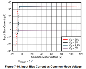
for this INA241A, it is a current sense amplifier, after it is inserted to the circuit, is the input bias current 35uA, equivalent to a 100K resistor connected to ground from the test point? assume the voltage of the test point is 3.5V. 

is there a diagram to help understand this Bias current.  what is the direction?

Thank you,

David

  • Hello David,

    There are two charts on the IB in the datasheet.  One vs VCM and one vs Vsense.  This is a good indication of the IB expected. You could also simulate.  

  • Hi Javier

    Thank you for prompt response, it is great chart for understanding the chip,  I have a question related to the chart of common-mode voltage,  Figure 7-16. let's assume the Vs = 2.7V, and assume the current flow into the pin(sink) is positive.  how can the current flow into the chip before the Common-mode voltage turns positive?  

  • Hello David,

    Internal there is a current pump and that is how there is an ability to go below VCM =0V.  This also give a lower voltage to feed the input stage bias current from the inputs.

    Regards,

    Javier

  • Hi Javier

    This is critical information to me, because I am using the chip with TPS61196 to get accurate current monitoring.  here is the thread.

    https://e2e.ti.com/support/power-management-group/power-management/f/power-management-forum/1255676/tps61196-board-not-working

    what I did here is using one INA241 cross each of the current sensor R28, 29, 30, 31.  

    the problem is that the TPS61196 will drive a current out to the loading path to detect if there is a load. if INA241 sink a current will disturb the detecting process of the TPS61196. 

    this is the waveform that without the INA241,  yellow trace is no load, and pink trace is with LED load. this is captured on the TPS61196 demo board. 

    here is the waveform from my design, basically copied from the demo, except added the current sensing circuit.   yellow trace has load, pink trace is not load for comparison. 

    both of the trace are in the negative voltage range, I couldn't explain before you explained that the INA241 in the path may sink current to the chip. I guess that could be the reason. 

    I am not sure if you are in the same support team as power supply. could you please have a look at my design and give me some judgement? if the insert of INA241 will interfere with the TPS61196. if INA241 not fit in this application, is there other solution that can monitor current and has high input impedance won't affect TPS61196 start?

    Appreciate your help. 

    thank you very much, 

    David 

  • page4.pdf

    here is the full page of the schematic.

  • Hello David,

    I am not an expert on the TPS61196.  Let me take a look at the device and if I cannot figure it out I will bring in those experts.

    Regards,

    Javier

  • Hello David,

    Just from my knowledge of the INA241 this could be the issue.  If there is now current then the INA241 still needs to bias the input stage.  It requires the current from somewhere to bias the input stage.  I assume that it gets the current from the IFBx pins when the output is off.  I read the datasheet and the startup current on of 10µA or 200µA is close to the input bias current is close to the value going into the inputs of our device.

    As for another solution do you need the current average or do you need to sample the current when the PWM is switching?  If you need average maybe some filtering and our device like the INA190 or the INA186 with very low input bias current.  If you need to get the current at the PWM frequency then I think this will not help an maybe a high speed amplifier will work.  

  • Hi Javier,

    Once I removed the INA241, then the TPS61196 will work. the reason I choose INA241 is its high common mode voltage. because the TPS61196 will generate around 80V on the LED chain. when the PWM turns off, I guess there could be transient common mode voltage on the input close to that value. 

    both INA190 and INA186 will work if their 40V Max common mode voltage will tolerate the output of the TPS61196. 

    Thank you very much for your help.

    David

  • Hi Javier,

    it is clear that INA241 will affect TPS61196 initializing. INA190 and INA186 may not work in this case because TPS61196 is a switching mode boost regulator. the output voltage could go to 80V in the design. and I am not sure during the current regulation process if the gate will archive this voltage during the transient.

    I added an analog switch, TMUX8019, it will be a perfect solution if it works. could you please help me review the schematic? 

    Thank you,

    David

    current_sensor_fix.pdf

  • Hello David,

    Two concerns.  The 10K resistors to GND and the current running through them.  Another thing is the On resistance at low voltages for the switches.  

    Regards,

    Javier