This thread has been locked.

If you have a related question, please click the "Ask a related question" button in the top right corner. The newly created question will be automatically linked to this question.

INA851EVM: How to use single power supply mode?

Part Number: INA851EVM
Other Parts Discussed in Thread: INA851, INA821, INA828, INA849

I want to try the single power supply mode. So I connect the benchtop power supply's positive (9V) to pin3 of J1. And then short the pin1 and pin2 of J1 and connect them to power supply's negative. But in this configuration, the EVM does not work. Why? Is there any reference design for single power supply of INA851? Thanks!

  • Hello Fan,

    The INA851 is a precision instrumentation amplifier, where the input stage of the INA851 device is similar to many other standard instrumentation amplifiers used in industry such as INA849, INA821, INA828, etc.  

    It is important to consider the input common-mode voltage range of the instrumentation amplifier, to ensure the INA device remains in its linear region. The INA851 datasheet specifies that the input voltage requires a headroom of 2.5V above and below the (Vs-) and (Vs+) supplies.

    If you are attempting to use the device with unipolar 9V supplies, with (Vs-) = GND, both INA inputs need to be at least 2.5V above the (Vs-) negative supply (GND), and 2.5V below the positive (Vs+) supply.     

    Therefore, if for example, you require to perform a measurement, where the negative input (IN-) is connected to GND, where one of the inputs is grounded, the device will require bipolar Vs(+) and Vs(-) supplies, where the negative supply needs to be more negative than <-2.5V below GND.

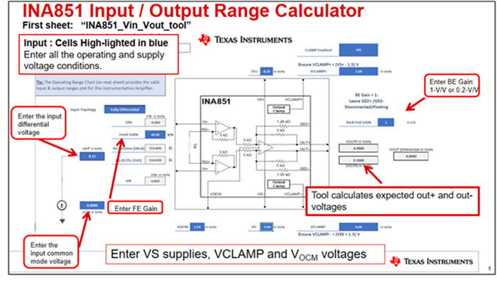
    The INA851 is similar to standard instrumentation amplifiers, the main difference is that incorporates a fully-differential amplifier output.  Each amplifier inside the INA has it’s own input and output swing limitations.   These limitations combine into an overall input differential and common mode voltage versus output swing range limitations. This relationship can be complex, therefore, we offer an excel calculator to verify the device is inside the input/output linear range.  

    You can download the excel tool on the link below and verify the amplifier is in range:

    INA851 Input-Output Range Design Calculator

    The tool consists of two sheets:

    On the first sheet, “INA851_Vin_Vout_tool”:

    The User fills the highlighted cells in blue with required voltages: VS+, VS-, Front-End Gain, Back-End Gain, Input differential voltage, input common-mode Voltage, VOCM voltage, VCLAMP+ and VCLAMP- (if Clamps Enabled). The Excel provides resulting VOUT+, VOUT-, and VOUT differential voltages.  The tool highlights in red any voltage out of range, and displays warnings in red if the device is outside of linear range.

    Similarly, the second sheet,  the tool provides an Operating Range Chart provides with the valid input & output ranges for this Instrumentation Amplifier. Use VICM to scroll bar to adjust the input common mode voltage.

    Attached is a pdf document with instructions:

    INA851 Input and Output Range Design Calculator Instructions.pdf

    Please let me know if you have questions.  If issues persist, please let me know the input signal voltages, ie, the input common-mode voltage, input differential voltage, gain requirement, as well as the  output voltage range requirements, that is the differential output voltage and the output common-mode voltage range requirements in the application.

    Thank you and Regards,

    Luis

  • Hi Luis,

    Thanks for your reply. It helps a lot.

    I have another question about INA851. What will happen if I leave the VLCAMP+/- open? From the block diagram, the opamp inside takes power from VS pins and VLCAMP pins. Does that mean it will still work when VCLAMP pins are open? I did quick check on the EVM and it looks good.

  • Hello Fan,

    We can't provide assurances of proper operation if VCLAMP+ and VCLAMP- are left floating or open.  If not using the clamp function, connecting the VCLAMP pins to the supplies will ensure proper operation, and reduce uncertainty of any potential distortion on the output signal due to the clamp pins having a voltage below the supply level.

    If you are not using the VCLAMP+ and VCLAMP- inputs, the datasheet recommends connecting these pin to the VS+ and VS- respectively.

    Thank you and Regards,

    Luis