This thread has been locked.

If you have a related question, please click the "Ask a related question" button in the top right corner. The newly created question will be automatically linked to this question.

VCA810: VCA810

Part Number: VCA810
Other Parts Discussed in Thread: VCA822, LMH6503, LMH6505, VCA821

Hi, I'm using VCA810. The deviations of positive and negative cycles of the input signal are high. For ex:
1. Gain = 55.4865 (with external resistor block and VCA810) Input : +- 20mV
Result :  Positive cycle of the signal deviation : Expected voltage x 1.22             
               Negative cycle of the signal deviation : Expected voltage x 1.08

1. Gain = 5.5742 (with external resistor block and VCA810) Input : +- 20mV
Result :  Positive cycle of the signal deviation : Expected voltage x 1.12      
               Negative cycle of the signal deviation : Expected voltage x 1.07

1. Gain = 110.2018 (with external resistor block and VCA810) Input : +- 20mV
Result :  Positive cycle of the signal deviation : Expected voltage x 1.25 
               Negative cycle of the signal deviation : Expected voltage x 1.105

1. Gain = 167.5665 (with external resistor block and VCA810) Input : +- 20mV
Result :  Positive cycle of the signal deviation : Expected voltage x 1.2      
               Negative cycle of the signal deviation : Expected voltage x 1.07

1. Gain = 14.0665 (with external resistor block and VCA810) Input : +- 20mV
Result :  Positive cycle of the signal deviation : Expected voltage x 1.13     
               Negative cycle of the signal deviation : Expected voltage x 1.05

As you can see above, each signal deviates approximately 1.2 at positive cycle, 1.08 at negative cycle. Is there an explanation for this situation? Because fault error like fixed. Thanks for advance. 

  • Hi Betul,

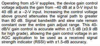
    This deviation can be attributed to the 40dB/V gain control. As the datasheet states, the gain control is accurate within +/-1.5dB (or equivalently about 1.2V/V).

    Please let me know if you have any other questions.

    Thanks,

    Nick

  • Hi Nick,

    Actually, I'm using VCA822 like VCA810. Each component results are same for deviation. Which one is more accurate? Is there a component with better values that you can recommend? As the gain increases, the error increases with it for VCA810. The difference between positive and negative cycles increases. What should I do for this to correct the signal?

  • Hi Betul,

    VCA822 is the more accurate device. You may also look into the VCA821, LMH6505, and LMH6503 as they have better accuracy as well. 

    Since these devices have internal gain adjust circuitry, there is no way to improve the accuracy of the gain unfortunately. What error margins are you looking to achieve?

    Thanks,

    Nick

  • Hi, Nick,

    I want to use VCA822 with 100V/V gain configuration. Between 50V to 100V/V gains are more accurate than 0V to 50V/V for VCA822. 

  • Hi Betul,

    The VCA822 has a very linear performance over its gain range.

    As section 9.2 states, the VCA822 offers a typical gain accuracy of +/-0.1dB. Depending on varying conditions, that could range up to +/-0.3dB (such as operating temperature). Because of the linear performance of the VCA822, this accuracy will be consistent for the entire gain range.

    Thanks,

    Nick

  • Thank you Nick.

    Could I use VCA822 device as cascade structure ? To obtain 1000V/V gain, I will configure first VCA822 device as 100V/V gain structure, the second one is 10V/V gain structure. 

  • Hi Betul,

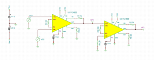
    You can cascade two VCA822 amplifiers together like I have shown below.

    One thing to take note of is the output voltage swing limits in this configuration. For a gain of +10V/V and amplifier power supply of +/-5V, the output voltage swing is about +/-4V depending on the output load. Depending on the output of the first stage, the output of the second stage may be clipped at +/-4V.

    Also make sure to pay attention to the input voltage, as the device can take an input from -2.1V to 1.6V.

    Thanks,

    Nick