This thread has been locked.

If you have a related question, please click the "Ask a related question" button in the top right corner. The newly created question will be automatically linked to this question.

OPA188: opamp design

Part Number: OPA188

Hi Art, 

I have tested the circuit, instead of Summing amplifier I used switch only. It's working fine. 
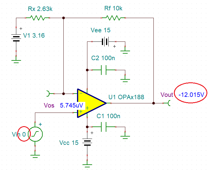
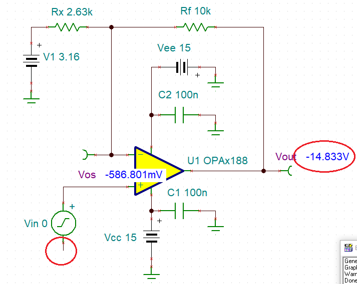
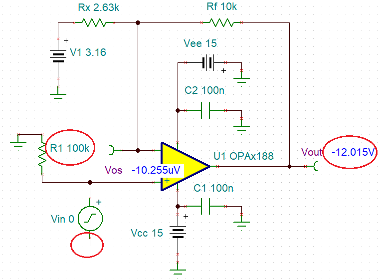
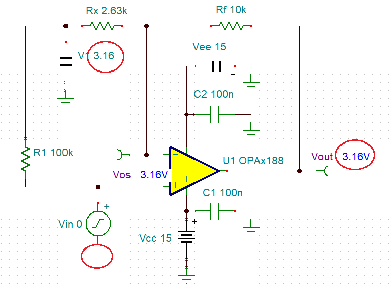
One issue I am facing is in floating input condition. 
Whenever no input is applied on Non-inverting terminal, output is around 400mV. Is this due to input Offset voltage? 
Can you guide me to reduce this. 

For the current scenario, I controlled it through software by giving fixed values. But please give a solution, that I can improve in hardware.

  • Vimukth,

    Whenever you float the input, the input bias current (IB) will cause the output to move towards one of the rail (depending on IB polarity) until the output transistors get trioded. As shown in the condition of AOL, in the case of OPA188 this occurs around 0.5V from either rail - see below.  Thus, in order to avoid it, you must control input at all times or clamp the output with external components.

    If you need further assistance, please include schematic and voltage supplies used (a picture is worth thousand words).

  • Marek, 

    Thank you for your clarification. 

    Here attaching my circuit for your reference. 

  • Grounding the input results in Vout at -12.015V - see below.

    Floating the input causes the output to collapse on negative rail - see below.

    Adding R1 pullup resistor to ground while floating Vin keeps the output at well-defined level  - see below.

    To control Vout, you may connect R1 to a different voltage while floating the input - see below.