This thread has been locked.

If you have a related question, please click the "Ask a related question" button in the top right corner. The newly created question will be automatically linked to this question.

OPA380: Working of the Circuit

Part Number: OPA380

Hi, 

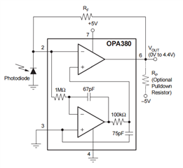
I wanted to work on OPA380 in my lab and got confused with the internal circuit given in datasheet. 

I can somehow make out that bottom opamp is taking voltage of pin 2 and applying a high-pass filtering at 2.3Khz and then a low pass filter at 21.2Khz, on lower frequency it works as a buffer. 

So what is actual working concept of this circuit, especially the bottom opamp. Can this circuit work just by giving a Threshold voltage at non-inverting input of top opamp? 

Thanks
  • Hello Swapniil,

    Could you share more about how you intend to use the OPA380?  Are you considering using the amplifier in a non-inverting configuration?  The biasing which occurs at Pin 3 (non-inverting input) assists with the transimpedance functionality of the OPA380, which expects a current signal input at Pin 2 (inverting input).

    The top op-amp utilizes the features of the high-impedance inverting input & RF feedback resistor to operate as a transimpedance amplifier; the bottom amplifier utilizes proprietary design to function as an auto-zeroing op-amp.  The OPA380 targets high precision with a low 1/f (flicker) noise.

    Once I know more about your potential application, I can better assist with your questions and design goals.

    Best,

    Alec

  • Hi Alec,

    I am starting to learn about the IC and wanted to start with the same configuration as given the above photo. Could you please help me with the working of bottom opamp for which you said it is an auto-zeroing opamp. I am not able to devise its working of auto-zeroing. On googling various transimpedance amp, I didn't fing this bottom opamp circuit anywhere. 

  • The datasheet says:

    The OPA380 series op amps use an auto-zero topology with a time-continuous 90MHz op amp in the signal path. This amplifier is zero-corrected every 100µs using a proprietary technique.
    […]
    Zero correction occurs at a 10kHz rate, but there is very little fundamental noise energy present at that frequency due to internal filtering.

    There is no 10 kHz oscillator shown, so it appears that that schematic alone does not explain everything.