Other Parts Discussed in Thread: LM567C
Hi,
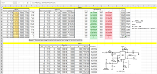
How can we replace LM566 with LM331?
if we are going to translate LM566 Vin to LM331 Vin.
Regards,
Mirthunraju M
This thread has been locked.
If you have a related question, please click the "Ask a related question" button in the top right corner. The newly created question will be automatically linked to this question.
Hi Mirthunraju,
I recalled that we discuss the product 5 months ago in the following thread. Has the Voltage to Frequency requirements changed?
Best,
Raymond
Hi Raymond,
Yes, the voltage to frequency requirement is the same.
but required Vin voltages (U6.5) are mentioned below from our practical value. Which should be translated to LM331 Vin.
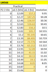
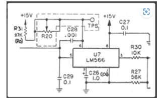
Regards,
Mirthunraju M
Hi Raymond,
From our previous conversation,
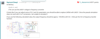

As you said, "I would suggest to place the LM331 on a perfboard or breadboard and check it out. 155.85Hz is in the low range of LM331 and it should work".
We have tested the LM331 IC practically but can't get the expected frequency (mentioned below) and 50-50% duty cycle.
Theoretically, Vin=2V -> Fout= 153.5 is correct.
But practical, Vin=2V ->Fout =1.28Khz and also can't achieve 50%-50% duty cycle.

How can we achieve 50%-50% duty cycle?
Regards,
Mirthunraju M
Hi Mirthunraju,
Could you remind me what is the LM566 or LM331's end application?
Can you send me the following Excel file or .txt file? I need to plot out the V-to-freq relationship.
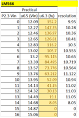
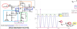
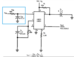
I recalled that your LM566's V+ and V5 are AC signals, therefore the subtraction is also AC in frequency. In LM331, the input is DC and convert from DC to frequency. So (V+ - V5) signal in AC in frequency and needs to be convert it the equivalent DC with a level shift likely. So I do not know how you made the AC to DC conversion. In LM331 circuit, a heavy LPF is used at Vin with fp = 15.9 Hz as it is shown in the diagram below. If you enter the corresponding DC value at Vin in LM331's suggested circuit, the obtained results should match the V-to-F conversion from the transfer function (also you may take into account of errors from component tolerances).
Anyway, I have ordered 2 LM331 samples from our TI sample store, and I can check it out in the lab. The sample will arrive in a week, and it may take another week for me to get results in the lab. Due to the thanksgiving holidays, I may be able to get it back to you by end of the month. Please let me know if this is acceptable.
Best,
Raymond
Hi Raymond,
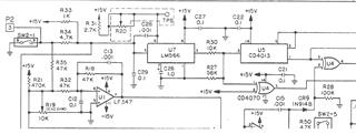
LM566 end application: - U7-> LM566 is connected to the U5->CD4013 & U4-> CD4070 as input.
P2 Connector pin3, we are not sure about whether it is AC or DC input. but right now, we are testing with DC as input to P2.3.
and while probing at U7.3 we captured the below waveform of LM566,
 ,
,
and also, I have attached Excel file below for your reference,
From our previous case we had discussed,
In LM566, when the voltage increased -> Frequency decreases.
In LM331, when the voltage increased -> also Frequency increases.
so, we had concluded as " if the input voltage of LM566 (Vcc - V_pin5) is translated to LM331's input in V/F converter" we can replace LM331 with LM566.
Regards,
Mirthunraju M
Hi Raymond,
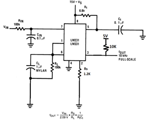
As correction in the circuit design. Now, it is updated which gives frequency but still duty cycle varies when increase in Vin.
There is no Fixed 50-50% duty cycle as LM566 provides.

Regards,
Mirthunraju M
Hi Mirthunraju,
The 50% duty cycles are the latest requirements, here is what Thomas has replied on LM331, please see the link below.

You may be able to feed a variable duty cycle PWM signals into a comparator with a reference voltage, which it may generate a 50% duty cycle PWM (this may be tricky to implement). Alternatively, you may use a variable duty cycle PWM compares with a comparator output with a fixed 50% duty cycle.
Have you considered to convert the V-to-F in a discrete circuitry?
If you have other questions, please let me know.
Best,
Raymond
Hi raymond,
How about using the LM567 internal VCO? Can we replace with LM566?
If possible can you arrange 2 samples of LM567 or else Tina or spice model?
Kindly, Help us with LM567.
Yes, we consider VCO in Discrete Circuitry.
Regards,
Mirthunraju M
Hi Mirthunraju,
You should be able to order samples from the site below. It will take time to receive the samples, even for us.
https://tisamples.ti.com/order/tisamples/en/
LM567 is also a legacy product and we do have spice model. LM567/LM567c are supported by DCC-CTS team. Please also check with the team over the E2E.
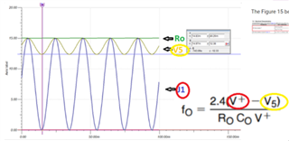
Regarding to the discrete V-to-F circuitry, from the previous inquiry, you want to convert (V+ - V5) to 155.85Hz. Are there any other requirements? What are frequency of V+ and V5 signals? Both signals are synchronized and it looks like that these are 60Hz in frequency. Please confirm.
Best,
Raymond
Hi Raymod,
The V+ and V5 both are DC input whereas V+ is fixed 15V and V5 is varied from 12V to 15V.
In our previous case, V5 is given as AC due to find the input range. Right now, the V5 value is 12V to 15V and the expected freq. output is mentioned below,
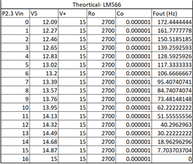

now it is clear both the V+ and V5 are DC input no AC input.
Regards,
Mirthunraju M
Hi Mirthunraju,
Thanks for the clarification per the input voltage requirements. It is easier to work around since the input voltages are DC now.
As you indicated, LM331 does not provide the output with 50% duty cycles pulses at 155.85Hz. Are you ok if we are offering a discrete solution for the V-to-I conversion?
Below is the transfer function.

In other words, fo = 59.2593*(V+ - V5), or fo vs. (V+ -V5) is a linear relationship, slope is 59.2593 Hz/V.
Best,
Raymond
Hi Raymond,
Also, I need to mention this case, where below mention readings are Practical Vs theoretically measurement of LM331.
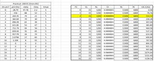
We need 12V to 15V as expected voltage input. Where, Lm331 with below configuration it supports 10V as maximum input voltage i.e., More than 10V it is 0Hz output frequency.
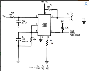
is there any possibility to operate in expected 12 to 15V. And also how to implement fo = 59.2593*(V+ - V5) in practical?
Regards,
Mirthunraju M
Hi Mirthunraju,
LM331 should be able to handle input up to 40V. If the max. input is up to 15Vdc, then Vcc need to be a bit, say 20Vdc.


We may also use an op amp and substrate (V+ - V5) before we input the signal to the LM331. Configure 59.2593 as the remaining terms from the equation in the blue rectangular box. You may make Rs = RL and derive Rt and Ct from the equation in blue box.
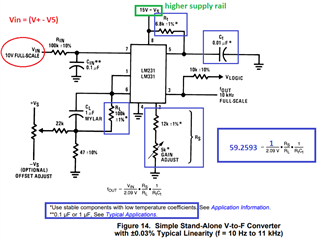
In terms of the differences observed between theoretical calculation and practical circuit, did you consider the tolerances of resistors and capacitors.
If you use 1% or 0.5% resistors, and low tolerance and low leakage capacitor, you should be able to get pretty close from the theoretical calculation. Regular ceramic capacitors typical have up to ±20% tolerance. If you use low tolerance COG or polypropylene, mylar, teflon, polyethylene or polystyrene capacitors, the differences should be small.
Please go to the lab and check out these changes.
When I receive the LM331 samples, I can go to our lab and check it out for you.
Here is the application note for LM331, if you do not have it.
Please let me know if you have other questions.
Best,
Raymond
Hi Raymond,
Is there any update?
If increase the VDD = 20V & Vin =12 still the out frequency is 0V.
As that setup provides only Vin=10V as full scale (maximum range of input)
And according to 59.2593 config. theory,
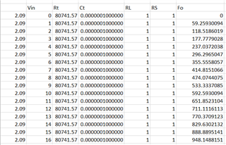
it does not match our expectations.
Let me also try the op amp to substrate (V+ - V5) this function.
Are still sure that LM331 can replace LM566? Because by this week we have to close the LM331.
Regards,
Mirthunraju M
Hi Mirthunraju,
Raymond is out this week - for this case, the only way to get the information you are looking for is to make the measurement on the bench, and we are still waiting for these devices to come in. Due to the samples delay, and the holiday schedule, we will have to unfortunately delay any more results until Wednesday of next week. Hopefully this can still help.
Regards,
Mike