This thread has been locked.

If you have a related question, please click the "Ask a related question" button in the top right corner. The newly created question will be automatically linked to this question.

PGA309: The PGA does not respond as expected in the config- CRC checksum issue?

Part Number: PGA309

Hello,

For a few days we have been trying to make working the PGA309. The hardware was implemented as on the Texas EVM board.

The EEPROM has been configured as follows:

EEPROM ADRESS (hex) Value (BIN) VALUE (HEX) DESCRIPITON
0x00 01001001 0x49
0x01 01010100 0x54
0x02 00000000 0x00
0x03 00000000 0x00
0x04 00000000 0x00
0x05 00000000 0x00
0x06 00000000 0x00 linerization disabled
0x07 00000100 0x04 external ref, Vexc enabled,Kexc=0.83
0x08 00000000 0x00 course offset =0
0x09 11010100 0xD4
One wire disabled, Out ampp gain=6, front end PGA gain=32
0x0A 00000000 0x00 Under over scale= disabled
0x0B 00000000 0x00
Default clock config, internal/external fault comparator disabled
0x0C 00000011 0x03 Resolution tp ADC=12bit
0X0D 00000110 0x06
Int tp mode selected, tp ADC enabled (continuous conversion mode)
0x0E 10000001 0x81
CRC1
0X0F 11111110 0xFE
0x10 00000000 0x00
T0=128 degres
0x11 00000100 0x08
0x12 00000000 0x00
Z0=0
0x13 00000000 0x00
0x14 11111111 0xFF
G0=1
0x15 11111111 0xFF
0x16 11111111 0xFF
Tend flag
0x17 01111111 0x7F
0x18 00000000 0x00
Zeta end flag
0x19 00000000 0x00
0x1A 00000001 0x01
Gend flag, CRC2=0xFE81
0x1B 01111000 0x78

We expect to have Vexc= 0.83xVref=2.739V

But we measure around 1V instead on Vexc.

Do you have any idea why?

We observed that in the datasheet the CRC HEX value does not corespond to the BIN value, is that related to our problem?


THANK YOU FOR YOUR HELP Slight smile

  • Calugar,

    1. You are correct.  The users guide checksum1 is inconsistent from the binary to hex result.   I did the calculation and the hex value looks correct.
    2. If checksum1 has an error.  The PGA309 will continuously read the EEPROM until checksum1 is correct.  The device will remain in reset state with Vout disabled.  If there is a checksum2 error, the PGA309 will disable VOUT, set the Gain and Zero DACs to their POR values, return to the read configuration register portion (first part of the EEPROM) of the loop, and then try to read the EEPROM Lookup Table again when the next temperature conversion completes. 
      1. The default value of Vexc is Disabled.  
    3. I do not see an obvious scenario where Vexc = 1V.  Maybe it is loaded down?  Is it connected to anything?  Can you disconnect it and confirm the voltage?
    4. The EEPROM tab on the EVM software allows you to read the EEPROM.  You can do this and use the attached spreadsheet to confirm your checksum is correct.  CHECK SUM.xlsx
    5. Did you use the EVM automated software to calibrate your system?  I always recommend doing this first even if you plan on developing your own calibration methods.  The reason is to confirm the hardware setup.  The attached file shows a step by step calibration using the EVM.  3365.pga309EVM software step-by-step example 9-22-2023b.pdf
    6. I hope this information is helpful to you.  Please  let me know if you have further questions.

    Best regards,

    Art

  • Hello,
    Thank you for your answer.
    I came back with some new informations after reading you. (In my first post I was giving a wrong value for Vexc, it was 2.4V and not 1V).
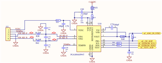
    Here you find the schematics that we used for our board - inspired by the PGA309EVM board


    As you suggested we measure Vexc whitout any connection + we put the registers config example from the datasheet. 
    And we have still the same issue -> Vexc is 2.4v. 
    We tried to change some configs but still the same Vexc=2.4V, even by writing a wrong config on the EEPROM ( a wrong CRC).
    We also tried to disconnect the connection between PGA pin and Vout and nothing change.
    We measured 214mV on the Vout in any case and our VCC is 3.3V.

    Concerning the EVM soft, we cant connect it to our board so we dont use it.

    Any idea? something wrong in the design?

    Thank you Slight smile

  • Calugar,

    Thank you for the extra detail.

    1. I think your checksum1 is not correct.  I did a quick excel spreadsheet to calculate the checksum and they do not look correct (see attached excel).  To double check my excel spreadsheet, I copied the eeprom data from the PGA309EVM and compared the EVM checksum to my excel version.  The two matched.
    2. One reason that I am not sure your checksums are incorrect, is that the excitation pin seems to output a signal.  If the checksum1 is incorrect, the Vexc pin should be disabled.  The output should also be disabled.  Can you double check your eeprom data listed in the initial post?
    3. I agree with your expatiation of what you think Vexc should be based on the register values.  You are using a ratiometric Vref (3.3V), and enabled the Excitation feature for range 1 (3.3V x 0.83 =  2.739V ).  You should double check the voltage on the reference pin to confirm that it is 3.3V.
    4. The EVM software is a powerful tool to help debug issues.  You should be able to connect some wires from the USB-DAQ-Platform connector J3 to your hardware and use the EVM software to debug.  Specifically, I think you only need to connect SDA, SCL, and GND.  I2C is open drain so you don't need to disconnect your microcontroller to connect the USB-DAQ to these lines.  When you use I2C on the EVM software, you need to make sure that "I2C Select" is selected in the block diagram tab.  The EVM schematic (https://www.ti.com/lit/df/sbor010/sbor010.pdf?ts=1701195231834 ) shows the pins you need to connect to (12, 13, and 21).
      1. If you can connect the USBDAQ to your hardware, you can use the EEPROM tab to read back your EEPROM.  This will be useful to me for debug.
      2. You can also do a register read, which will allow us to confirm how the part is configured.
      3. You should also be able to do a full calibration (assuming you can apply the input signals).

    calculating checksums.xlsx

    I hope this information is helpful to you.

    Best regards,

    Art

  • Hello Kay,
    Thank you for your feedback.

    1. Indeed the CRC1 was not correct, we tried by replacing the value by the correct one (CDB3)  and still have the issue.
    2. I'm undestanding the samething from datasheet but in our case the Vexc =2.37V in any situation.
    3. We check the Vref and it is 3.3V
    4.We understant the benefits of the EVM but unfortunately the USB-DAQ platform is way to expensive. It was not forsee in the development budget. Instead of the EVM platform we are using our MCU to write and after read the data in the EEPROM. The data is well writen.

    We checked your excel file and it is very helpfull. We want to configure the EEPROM with the same register configuration that you provide us for your evm.
    It is well clear for the "my checksum 1" sheet  but for the " my checksum 2", we don't understand why you have 53 values +1 for the CRC2.
    What are the eeprom adresses for them?

    In the datasheet exemple for CRC2 it is only the following values:


    Thank you,

  • Calugar,

    For checksum2, I am using a 17 point lookup table.  This is the maximum lookup table length for PGA309.  Using more points gives the best curve-fit, so I always use 17 points.  The only disadvantage to the long lookup is that there is a very short delay required for reading the table.  Since most applications have slow moving temperature this delay doesn't introduce any issues.  The 17 point lookup uses 3*2*18 = 108 memory locations.  The "3" comes from the fact that each point has a temperature, gain, and offset lookup entry.  The "2" comes from the fact that each table entry uses two bytes.  The "18" comes from 17 points and one END point.  Note that each row in my excel accounts for two memory locations.  Also, the very last entry in the table is the check sum.  108/2 = 54 where the look-up is 51 words, TEND, ZMEND, and GEND are the last three entries.  GEND is the checksum.  See more detailed lookup excel below.  The PGA309 users guide shows a short table for simplicity of explanation.

    eeprom.xlsx

    If you confirm that both checksums are correct, and you still find the Vexc is at an invalid value, than the following are possibilities:

    1. The device is damaged   
    2. The Vexc is disabled and the pin floats to some voltage
    3. The Vexc pin is overloaded (i.e. your sensor impedance draws too much current from Vexc).

    Best regards, Art