This thread has been locked.

If you have a related question, please click the "Ask a related question" button in the top right corner. The newly created question will be automatically linked to this question.

OPA991: too high distortion of the 60kHz amplifier

Part Number: OPA991
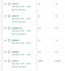
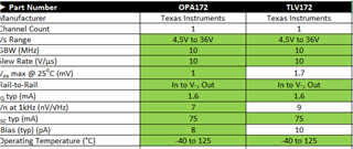
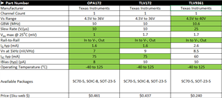
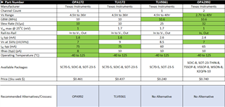
Other Parts Discussed in Thread: TLV9161-Q1, OPA172, TLV172, LMV641, LMV841, OPA992, OPA2991, TLV9361, OPA2992

Hi,

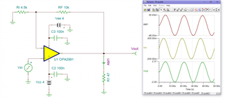
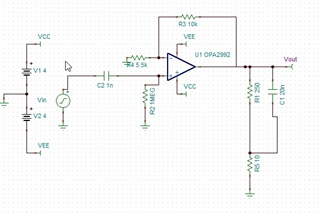
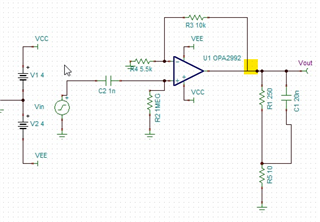
We're designing a product with analog amplifier. Signal: AC sinus 60kHz, gain of 3.2, power voltages +-4V, min. load of 40 oHm, max/ load capacity of 1nF, max. output voltage (w/o load) of 6Vpp.

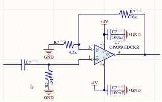
Application: not-inverting OP AMP, feedback of 10k, pull down of 4.5k.

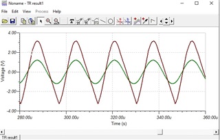
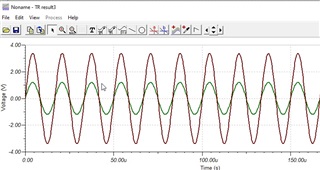
I've simulated this amplifier be MICROCAP (original TI spice model) and didn't see any problem. The specific part is the OPA991IDCKR.

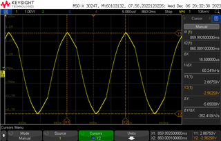
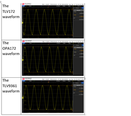
Right now we got boards and I am observing too high distortion with both low voltage operation on 47 oHm resistive load and high voltage (5.9Vpp) w/o load.

Please advise how to solve this issue. Maybe to replace this OP AMP with another one, some package/pinout ?

  • Hello, 

    Welcome to e2e! 

    With such a small resistive load, this is a lot of output current for the op amp to drive. 

    Here is a screen capture of a TINA sim: 

    I am assuming the input signal is ±0.93V since 0.93 x 3.2 = ±3V. 
    Please confirm if the circuit is different -- I didn't include the cap load since the OPA991 can easily drive a 1nF. 

    With this much current drive, the maximum output voltage for each swing is relative to the power supply and shown in Figures 6-14 and 6-15 in the datasheet: 

    at ±50mA, the max output voltage is a (V+) - 1.5V = 4V - 1.5V = 2.5V 
    The sim is showing something a little lower (2.37) to account for lower supply voltage - the datasheet curves are taken at full power supply of ±20V. 

    Is the 47 ohm resistance required? If so, I will help find an op amp with higher output load drive. 

    high voltage (5.9Vpp) w/o load.

    As for this above, I am a little stumped about what could be happening.... please verify that the circuit I've drawn above is accurate. If its not, could you share your circuit?

    All the best,
    Carolina 

  • Hello Carolina,

    See my schematic and the output 60kHz signal.

    Right now, I've found interesting discussion concerning very similar issue of the OPA991:

    https://e2e.ti.com/support/amplifiers-group/amplifiers/f/amplifiers-forum/999779/opa991-opa991-is-not-meeting-its-slew-rate-specification

     had written:

    As you can see these simulations are not close to the real-world hardware response I am getting.

    So, I guess that the OPA991 PCPICE model doesn't reflect its behavior. 

    My decision is to look for another OP AMP with the same package/pinout and replace the OPA991 on all boards.

    I've found the following parts: TLV9161-Q1, TLV9151DCK, OPA172IDCKR, TLV172DCKR.

    Please advise which of them is the best choose for our application. 

  • Hello, 

    Yeah it looks very similar to that earlier thread, in that case I feel confident saying the input (0.9V) is not large enough to trigger the full slew rate (with slew boost), see this article written by my colleague Ron Michallick for additional details: Ramping Up on Slew Rate

    Looks like the natural slew at that small input is less than 3V/us. 

    Since that is not enough, I searched through the parametric table for devices that meet the power supply and package requirement for these 23 results: https://www.ti.com/amplifier-circuit/op-amps/products.html#261006=DCK&1261max=8%3B180&

    From there, following the advice listed in the earlier mentioned app note, I compare GBW and SR to find a part without SR boost, 

    Of which only the following seemed to meet the criteria: 

    Since 3V/us was not enough, I recommend either the TLV172/OPA172. 

    I can test if these have slew boost for you but it will have to be next week. Please let me know. 

    All the best,
    Caro

  • Hello Carolina,

    Yes, I also think that both TLV172 and OPA172 are fit for our application.

    About LMV641/LMV841/LPV411, theirs slew rate is too low. 

    For example, see waveform of the LMV641 TINA simulation:

    And what about the OPA992? It features too high slew rate (32V/uS), and operates with high capacitive load (20nF):

    Best Regards and thanks for assistance !

    Michael

  • Hey Michael, 

    Yes the OPA992 would work, I was hesitant to promote it at first because this also has slew boost, however Figure 6-15 shows that with an input step of 0.9, the expected slew rate is 22 V/us. 

    The other thing to consider when implementing a solution with the OPA992 that the capacitive load driving is significantly less stable than the OPA2991. 

    The instability doesn't show in the simulation you ran because stability is a small signal measurement with fast transition time (think small step).  I recommend this training series: https://www.ti.com/video/series/precision-labs/ti-precision-labs-op-amps.html 

    Instability is worse at a gain of 1, luckily this configuration is in a gain so it will be easier to stabilize. 

    This doesn't mean that you can't use the 992 it just means that an RISO must be implemented in the highlighted section: 

    I would start with an RISO of 50 (as Figure 6-31 and 6-32 of the datasheet imply), adjust accordingly for acceptable overshoot/output settling time.

    All the best,
    Caro

  • Hi Carolina,

    In our application R5 (current sense resistor) operates as RISO for capacitive load. Its value is 10 oHm; I can increase it a bit (lets say, up to 20 oHm), but 50 oHm is too high resistance.

    I think it will be better to order some samples of the following parts: TLV9151IDCKR, OPA172IDCKR, TLV172IDCKR, TLV9361IDCKR, OPA992IDCKR, to evaluate each of them and to choose the best one for our application. 

    Thank you.

    Michael

  • Hey Michael, 

    That sounds like a great idea, please let us know the results.
    Do you know your regional sales contact to help you order samples? 

    All the best,
    Carolina

  • Hey Michael, 

    I have shared your contacts information through private message, I will delete your location since this is a public forum. 

    All the best,
    Caro

  • Hi Carolin,

    I've got the samples and tested OPA172, TLV172 and TLV9361. For active load (40-300 oHm) all behave similar; no visible distirtion for 60kHz sinus. But for hard capacitive load (300oHm+40nF in parallel; RISO of 10 oHm) I noticed differences.

    As I see, the TLV9361 is the best between the three, and OPA172 is the worst. 

    BTW, what difference between OPA172 and TLV172? Per my understanding, the "OPA" prefix related to BURR-BROWN heritance, correct?

    Michael

  • Hey Michael, 

    Good to hear the TLV9361 is a good fit for the application. Thank you for sharing 

    The TLV is a similar design to the OPA version with a lower cost and reduced performance, here is a comparison table. 

    As you can see in this scenario, the offset voltage is slightly higher, the input voltage noise is higher, and the input bias current is higher. 
    With the TLV9361 included, you can see it falls somewhere between the OPA172 and TLV172: 

    Here is the OPA2992 included in the comparison: 

    All the best,
    Carolina