This thread has been locked.

If you have a related question, please click the "Ask a related question" button in the top right corner. The newly created question will be automatically linked to this question.

LM741: Operational Amplifier Failure

Part Number: LM741
Other Parts Discussed in Thread: UA741,

Hello E2E design support. I reached out a few months ago regarding determining the failure mode of LM741CH op amps. I am reaching out again with some more information in hopes to find a possible cause for the observed failures.

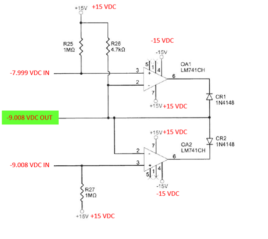
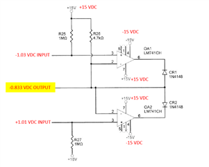
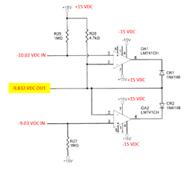
In the circuit there are 2 LM741CH ICs configured for a most negative auctioneering circuit. There are two input voltages (one for each op amp) and the output of the circuit should match whatever the lower of the 2 input voltages is. Below are 2 different measured scenarios where the op-amps failed. Pin 2 of the op amps is the output of the circuit below and should correspond to the lower of the two input voltages as shown. In both cases the output voltage measured did not correspond to either of the inputs.

The positive and negative rails of each IC were measured to be correct and no issues were found with the diodes at the output of the ICs or with the resistors. The input voltages were also verified to be within the input voltage specification of the LM741CH per the datasheet. Upon replacement of both ICs (OA1 and OA2) with new LM741CH chips the outputs were measured to be correct and corresponded to the lower of the 2 inputs. So we are still trying to determine what may cause the output to be out of tolerance with respect to the input voltage to the IC. Pins 1 and 5 for each op amp are not connected within the circuit and are left open. Any information is greatly appreciated.
  • Adam,

    What are the voltages at pin 6?  Is the output signal oscillating?

  • Hi Ron. The following is related to the bottom figure in the context above:

    Both voltages at pin 6 of each op-amp were observed to be stable and not oscillating. The voltage at pin 6 of OA1 (top op-amp with most negative -10.02 VDC input) was measured to be -10.526 VDC. Although the output voltage (pin 2) of -9.832 VDC is incorrect (should be very close to -10.02) the voltage measured at pin 6 of OA1 makes sense as this corresponds to a 0.694 V drop across diode CR1.

    The voltage at pin 6 of OA2 (bottom op-amp with -9.03 VDC input) was measured to be at the positive rail voltage of 15 V which also makes sense due to OA2's inverting input being less than the non-inverting input, pulling the output to the positive rail and that +15 V being blocked by diode CR2.

  • Adam,

    Does OA2 work correctly, meaning is output correct when lower input is lesser input voltage? Is the problem always with OA1 or can OA2 be the damaged chip?  It's a rare issue to see an op amp work but with a very high input offset error of 200mV.

    I recommend changing to a op amp with a higher ESD rating. 

  • Ron,

    On one of the units that we tested both OA1 and OA2 were faulty and we did not get the correct output voltage for either. For the other one however, OA2 was functioning correctly as shown below where the input of -9.008 VDC was also the output of the card. So the problem is not always with just OA1. In the case below the voltage at pin 6 of OA2 was also measured and was stable at -9.703 corresponding to an appropriate 0.695 V drop across the diode CR2. Which was the same drop observed and discussed above for CR1. 

    Do you know what could cause that kind of high input offset error for these ICs. It is not the first time we have seen this behavior change like this over time so we are trying to find out what is causing this to occur. It seems as if all of the ratings and characteristics of the LM741CH are appropriate for this use. Thank you.

  • Adam,

    When there is a failure, is the output always too positive (less negative)? That would suggest the same pin fails in the same way. 

    Normally I'd think that pin 2 is damaged because that point is common to both amplifiers. However the error voltage polarity coupled with a NPN input (data sheet section 7.2) makes me think pin 3 NPN transistor's gain is being destroyed. I'm asking if inputs or output go to a connecter (or a long trace). The ESD rating of UA741 is rather low.  Also, can input(s) be powered before op amp supply comes up?

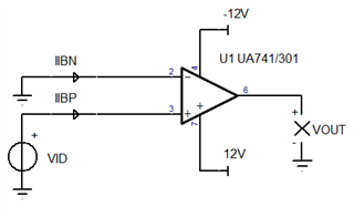
    Can you do bench tests on your samples? I can recommend some simple tests that may reveal more information about the failure mode.

  • Ron,

    For every failure observed with these ICs the output was always too positive. So yes that does make sense the same failure is occurring for each IC. The inputs and outputs of the ICs do go to PCB card edge connectors.

    Regarding the inputs and supply voltages, for all of the testing that we do the supply voltages are established and verified prior to the inputs to pin 3 of each LM741. For our clients application I can only assume that the supply voltages are present before the input voltages are. Although, I cannot confirm that is always the case.

    I would greatly appreciate some simple test recommendations however for these ICs specifically we no longer have them available for individual testing.

  • Adam,

    I understand that as the direct access to both pin 3's is possible. In the schematic there is no resistance between pin 3 and the unknown source of the input. No resistance and direct access is the key.

    Later this week, I'll run the simple tests in mind and post the setups and the data that can be expected for a good unit. 

    Do you need all the ratings and characteristics of the LM741CH? With a different op amp and some board changes, the application can be made more robust against being damaged. 

  • Adam,

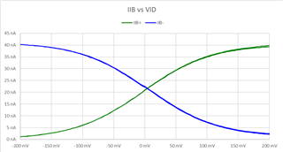
    While the setup is simple, the ability to read nanoamperes is needed for good units. It is OK to use one meter and run this twice.

    The current of a damaged unit may be much higher. 

    Vary the VID voltage and monitor IIB+ and IIB- currents. They should be similar and match current near 0mV 

    Vout should also change between low and high near 0mV 

  • Ron,

    Hope you had a good holiday and are having a good New Year. Thank you for the test setup and information! I will keep this in mind in the future if we get anymore failed units that we can get an IC from to test. 

    Regarding the LM741CH, this is the IC that is being used in latest design, so the latest design is more robust. However there are still units out there that just have the LM741 IC installed and we are trying to determine if these units are prone to the same failures we have seen in the past. In order to determine this though we need to figure out what the root cause is. Which is understandably difficult without having all of the information. Seems like an ESD event to pin 3 is definitely a possibility though.