This thread has been locked.

If you have a related question, please click the "Ask a related question" button in the top right corner. The newly created question will be automatically linked to this question.

OPA855: simulation for OPA855

Part Number: OPA855
Other Parts Discussed in Thread: ADS7046, OPA856

Hello Team,
We want to design a trans-impedance amplifier (TIA) using the opamp OPA855.
The ADC we are using is ADS7046.
The photodiode we are using is J-Series SiPM Sensors.


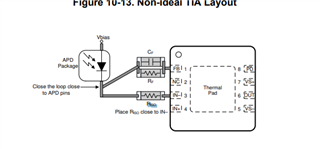
What is the need for Riso in the schematic?


Can you please provide the simulation file for the same circuit?
The Rf is 47E and the Cf is set to 10nF to get an output of approximately 470mV.
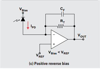
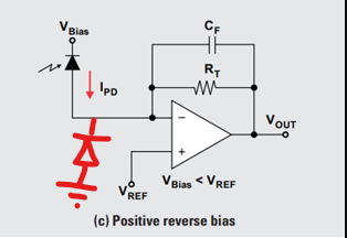
The photo diode will be connected in photo conductive mode with its cathode connected to a +ve voltage


  • Hi Vijay,

    In order to provide you with a simulation to meet your design requirements I have a few questions:

    1. I reviewed the J-Series SiPM Sensors datasheet that you provided. It shows a few different sensors in that family; could you share which sensor you are using exactly? The reason I ask is that the capacitance of each photodiode is different and the passive components used in a TIA application are sensitive to what capacitance the photodiode has.
    2. Can you share what input current is coming from the photodiode and what your expected output voltage is? The feedback resistor value is found by dividing the expected output voltage by the input current from the photodiode. Typically feedback resistors have values much larger than 47ohms so I want to confirm what your circuit needs are.
    3. What bandwidth do you need for your application?

    Another thing to note, the feedback capacitor is determined by the GBWP of the device, closed loop bandwidth needed, feedback resistance and input capacitance of the circuit. We have more information about TIA circuits here which includes a calculator for determining the necessary feedback capacitor value needed for circuit stability based on the above parameters. 

    To answer your question about Riso:

    The isolation resistor (Riso) is added to the inverting input of the amplifier to dampen the potential resonance caused by the trace inductance and the amplifiers internal capacitance. Riso should be a value between 10 and 20 ohms.


    Thanks,

    Nick

  • Hello Nick,
    Thank you for your reply.
    The photodiode we are using is a 3mm photodiode.


    What bandwidth do you need for your application?

    Can you please explain what is meant by this?

  • Hi Vijay,

    Thank you for sharing the photodiode you are using so I can build the simulation files. Can you also share what the expected input current and output voltage are? 

    My assumption is that you will be sending some kind of pulse signal into the amplifier. In order to match that signal on the output, the amplifier needs to have sufficient bandwidth. The frequency of the input signal and the rise time of the pulse are dictated by the bandwidth of the amplifier. For example, if you are trying to achieve a certain rise time of the pulse signal, the equation is rise time (tr)=0.35/bandwidth. Based on this, can you share what bandwidth you need for the application?

    Thanks,

    Nick

  • Hello Nick,
    Thank you for your reply.
    Now the output voltage varies only between (3uA * 47E = 141uV) and (10mA * 47E = 470mV).
    About the bandwidth of the system, the LED will be turned on every 30uS and the ADC will sample the data in both the on and off time of the LED.
    The LED will be on for about 15uS.
    We are using Positive reverse bias with a bias voltage of 3V and Vref of 3.3V

  • Hi Vijay,

    Thank you for providing these additional details. Based on these details, I believe that the OPA855 is not the best choice for your design since it is a decompensated amplifier. Meaning it must be configure in a gain of 7V/V or higher in order to have stable operation. By using such a small feedback resistor, you are not configured in a gain of 7V/V and therefor the output will be unstable.

    The OPA856 is a similar device to the OPA855 except that the OPA856 is a unity gain stable device which means it can be operated stable in lower gains.

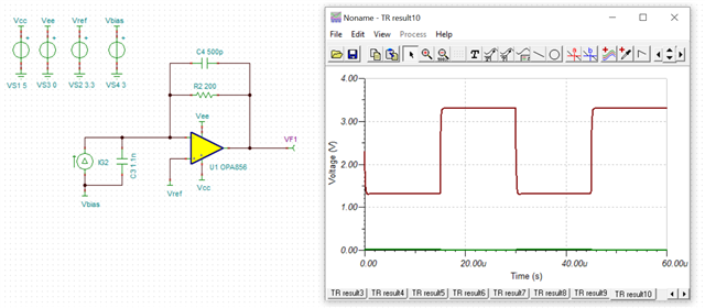
    I am curious as to why you are choosing a feedback resistor of 47 ohms for your design. I have created a simulation and it shows that you are not achieving the full output swing of the OPA856 by having a feedback resistor of 47 ohms. The simulation I have provided below, uses a feedback resistor of 200 ohms.

    OPA856_E2E.TSC

    I selected the input capacitance based on the photodiode capacitance from the datasheet you provided. This simulation shows an input current of 10mA. The feedback capacitance was calculated using the TIA calculator from the link in my first reply.

    Please let me know if you have any questions about the simulation file.

    Thanks,

    Nick

  • Hello Nick,
    Thank you for your reply.
    The minimum gain of the OPA855 is 7V/V.
    Since the input of the TIA is current and the output is voltage how to calculate the gain of the TIA?
    Also, the simulation of the circuit OPA856 works well for our application.
    However, when I replaced the OPA856 with OPA855 in the simulation, the simulation showed some error, can you please check why it is?

  • Hi Vijay,

    I was actually incorrect in saying that the 200 ohm feedback resistor was not large enough to achieve a gain of 7V/V. The gain of a TIA (transimpedance gain, dBΩ) is equal to 20*log(Rf). That is to say that the feedback resistor is equivalent to the V/V gain in TIA applications. Therefore, the resistor values you chose are large enough and would not cause instability.

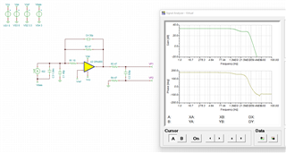
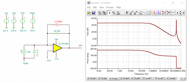
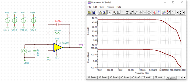
    I looked into the simulation further. The reason that there is an error in the simulation when using the OPA855 is because of large gain peaking in the bode plot caused by a large feedback capacitor. Here is the frequency response plot when using a 500pF capacitor:

    And here is the frequency response plot when using a 50pF capacitor:

    I also looked at the simulation of the OPA856 I provided and there is a small amount of peaking in the frequency response for that device as well. Decreasing the feedback capacitance will lower that peaking and increase the bandwidth.

    Thanks,

    Nick

  • Hello Nick,
    Thank you for your reply.


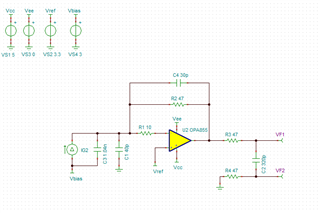
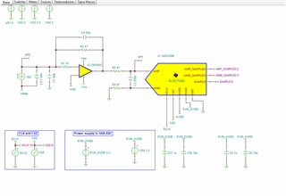
    The photodiode's capacitance is 1040pF and we are using a TVS diode to GND whose capacitance is 40pF.


    The value of Riso is set to 10E.


    The 47E resistors and the 320pF capacitor at the output of the TIA form the kickback filter for the ADC ADS7046.

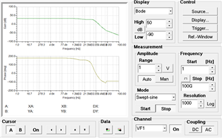
    Why do we have an issue with the phase margin?
    Will it cause any issues with the system?

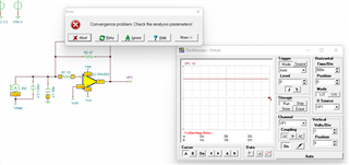
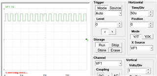
    Sometimes the simulation shows the following error. sometimes immediately after running the simulation or sometimes after running for 2 or 3 seconds
    What could be the reason for that?

  • Hi Vijay,

    I have set up my simulation like the one you show in your latest reply. If I try to run a transient analysis for more than a few milliseconds, I get the error that you are seeing. This seems to suggest that there is some instability with the circuit design. 

    When I generate a frequency response of this circuit, I see some dB peaking which suggests that stability may be a concern. So I adjusted the feedback capacitor to 50pF to decrease the gain dB peaking. After doing this, I do not get any convergence errors when I run the simulation for 5 or more seconds. 

    I also ran a stability analysis and there is phase margin of about 70 degrees. I suspect the capacitive loading due to the kickback filter caused the possible instability.

    Thanks,

    Nick

  • Hello Nick,
    Thank you for your reply.
    Attached is our final schematic and their analysis results.
    Please review them and correct them if any corrections are needed.


    Please review them and correct them if any corrections are needed.

    Also, the ADC we are using is ADS7046.
    Is there any method to simulate the ADC in TINA TI?

    Looking for your reply

  • Hi Vijay,

    From my explanation from my previous reply, there is a risk of instability if you use a 30pF feedback capacitor. Increasing the feedback capacitor, to say 50pF,  will provided a larger phase margin.

    Also, it is possible to simulate with the ADC in TINA TI. If you go to the product page for the ADS7046, under the design and development tab you can download a zip file containing the .tsm file. This is the macro for the ADS7046. In order to insert the macro into the simulation file, in TINA select Insert -> Macro. Then you can browse to where the .tsm file is saved. The steps are explained here.

    Thanks,

    Nick

  • Hello Nick,
    Thank you for your reply.
    We get the same error (convergence problem) after running for some time if the feedback resistor is changed to 50pF.
    Can you please confirm the same?


    Also, the simulation with the ADC is not working properly.
    Can you please guide me?

    OPA855_New.TSC

  • Hi Vijay,

    Thank you for sharing the new schematic file. 

    Can you share what you mean by the simulation with the ADC is not working properly? Are you referring to the convergence error that you are seeing or are you observing something else?

    It seems that the convergence error may be a result of more capacitive loading from the sampling capacitance of the ADC. I am looking into this more thoroughly. Increasing the feedback capacitor of the TIA would help reduce any convergence issues, but would decrease the bandwidth some. You should still have sufficient bandwidth for the application you described.

    Thanks,

    Nick

  • Hello Nick,
    Can you please check whether the configuration of the TIA is correct or not? (not considering ADC).
    We still get convergence errors.

    I belive the issue with the ADC is due to some other reason.


  • Hi Vijay,

    The configuration of the TIA is correct. When I simulate the file you attached, I am seeing an expected output. You may need to tweak the feedback capacitance a little bit to remove some of the spiking caused by the sampling of the ADC. I increased the the feedback capacitance to 100pF and this removed most of the spiking.

    Thanks,

    Nick

  • Hello Nick,

    I have a similar problem. Can you please give me some advice?

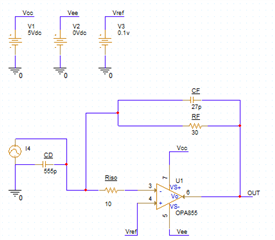
    I use OPA855 as a TIA. The SIPM's output voltage is 32mV, rise time is 1.3ns, capacitance is 555pF.

    I calculate the bandwidth is 270MHz by the equation is rise time (tr)=0.35/bandwidth. But I don't know whether the value of RF and CF are correct.

    Here is the circuit:

  • Hi Yuan,

    Here are a few comments:

    • The rise time equation I am referring to provides a calculation for what the rise time of the output voltage of the TIA, given its certain closed loop bandwidth. So as you calculated, you would need the TIA to have a closed loop bandwidth of 270MHz in order to achieve a rise time of approximately 1.3ns. In order to achieve the large of a closed loop bandwidth results in a very small feedback resistor value
    • Having a small Rf value will ultimately result in a very small change in the output voltage, which is dependent on what the SiPM output current is. The output voltage will be equivalent to (Vref) +/- (Rf * output current of SiPM). The plus or minus is determined based on whether the SiPM is sinking or sourcing current. Depending on the current, if Rf is 30 ohms, this could result in a very small change in the output voltage that could be lost in later stages
    • TIA applications commonly take a small input current and convert it to a larger voltage swing for later signal processing. I can help you determine values for Rf and Cf based on what your input current range is and what your output voltage swing requirements are. If you have any output voltage rise time requirements, please share those as well. That being said, it may not be possible to achieve a rise time of 1.3ns. However something around 5ns may be possible.

    Also, could you please start a new thread using the Ask a related question or Ask a new question button at the top of the screen. This will help keep both threads clean. I will be more than happy to continue support on a new thread.

    Thanks,

    Nick