This thread has been locked.
If you have a related question, please click the "Ask a related question" button in the top right corner. The newly created question will be automatically linked to this question.
Hi,
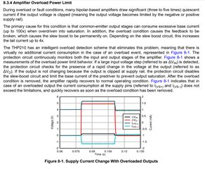
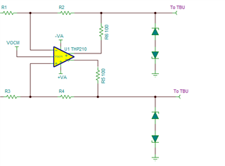
I using THP210DGKT for single-ended to differential signals. I wonder, How to work the Overload power limit and Current limit features.
Does THp210 limit itself at Overload power and high current or does it self-destruct? I want to learn.
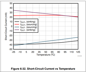
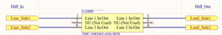
I want to current limit for differential output. I think out the Transient Blacking Unit for the output, but this component's minimum limit is 50mA. I think need less than THP210 Short-circuit current (±31).
I would be glad if you could inform me about this subject. If you have any other suggestions, I would be happy to hear them. Thanks for your help!
HI Emre,
The THP210 can drive a typical continuous current of ±31mA at its output. Please note the datasheet output current drive specification is typical, and there is variation on the current drive capability depending on the device and circuit conditions. As any other amplifier, the THP210 output current drive capability varies with temperature and output voltage swing as shown on Figure 6-30 and figure 6-32 of the THP210 datasheet:
The THP210 Amplifier Overload Power limit feature is only intended to disable the internal slew-boost circuit when the device is overdriven into saturation. This is to prevent the THP210 output stage of the device to consume excessive current when the output voltage is clipped or when the output limited to the supply rails. In essence, there is an internal monitor circuit that disables the slew-boost circuitry if the output is clipped to the supply rail, and prevents the slew boost circuit to be permanently on. Please note, this feature helps the device to recover fast from an overload condition, and prevents additional excessive current consumption at the base current on the bipolar common-emitter output stage.
However, this feature does not limit the the output current drive of the THP210. The THP210 does not incorporate an output current limit function; and the THP210 output stage will drive as much current until reaches its current drive capability.
From the THP210 perspective, the device can withstand to drive continuously the output short circuit current without damage. The absolute maximum ratings table also specify the maximum input and output current the device can withstand without damage.
If you have additional questions, please provide a full schematic, and please describe the which circuit needs to be protected, and describe in detail the maximum fault overvoltage/overcurrent conditions that the devices need to be protected for.
Thank you and Regards,
Luis
Hi Luis,
Thanks for your detailed reply.
I'm attempting to protect the THP210's output from short-circuit currents. The solution I'm seeking involves interrupting the line if the system draws a current exceeding a specified value. The TBU-DF085-050-WH TBU device imposes this limitation at 50mA. I'm looking for a similar device that operates at 20mA and is not require any energy. TBU's schematic is below.
While I can achieve this with a combination of a MOSFET, shunt resistor, and op-amp, I aim to minimize using multiple circuits.
What are the anticipated outcomes when the output of THP210 experiences a momentary short circuit, causing a high current draw?
HI Emre,
The THP210 output stage will attempt to drive the output stage to the target voltage, until it reaches its output current capability. For example, if the output pins are shorted to GND, and the device attempts to drive the OUT+ to +5V, and OUT- to -5V, the OUT+ will source the short circuit current of around +31mA and the OUT- will sink around -31mA output current.
Per the absolute max rating table, in a fault, if the output stage is shorted or driven to a voltage externally, the output pins of the device can withstand a max/min output current of ±50mA.
In addition to the TBU device, which will activate if the 50mA current is exceeded, you could add bidirectional TVS diodes at each output, and series resistors, to help prevent over-voltage condition and ensure that the voltage at the output pins do not exceed the supply rails, and prevent damage. For example, adding small series resistors of ~100Ω inside the feedback loop, in combination with the TVS diodes and the TBU device can help clamping the output voltage and limiting current.
Thank you and Regards,
Luis