This thread has been locked.

If you have a related question, please click the "Ask a related question" button in the top right corner. The newly created question will be automatically linked to this question.

THS3491: unity gain and transformation isolation in cascade

Part Number: THS3491
Other Parts Discussed in Thread: THS3091, THS3095

Hello:

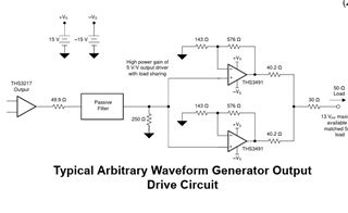
I am wondering if THS3491 can be put in unity gain as shown in the attached pdf file, drive low current load followed by another THS3491 driving into another low power load?

Our pulses are up to 12v/-5v in amplitude, with very fast rise/fall time up to Meg Hz max rate.

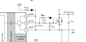
One side has unknown references as shown ( REFX), with supplies referenced to REFX. The other side is referred to std GNDS as shown.

Can this be simulated - or with any other very high slew rate wideband current feedback opamp using TINATI?

Any clarification will be highly appreciated.

-r

  • oops: forgot to attach the file.

    pl see this post.

    -rths3491_isolated_wb pulse_tx.pdf

  • Hi Robin,

    The THS3491DDA is not designed to have unity gain configuration. The DDA package has a higher bond wire inductance interacting with the loop phase margin and so stability is hard to achieve when in unity gain configuration. Please see this E2E thread for more details on this (here).

    I would be happy to help find a suitable solution, however. I have a few questions about the file you attached in order to understand your application better:

    1. In the first stage, you have the REFX signal. What is the voltage range of REFX you plan to use?

    2. The circuit you designed has two feedback loops. One with the 50 ohm resistor, the other with the 11kohm resistor connected to REFX in series with another 11kohm resistor. What is the purpose of the second loop (i.e. why is the 11kohm resistor connected to Vin-)?

    3. For the power supply requirements, can you elaborate as to why the supplies are referenced to REFX? Changing the supplies during operation will affect the dynamic range of the device as well as possibly affecting noise and distortion performance. On the second stage, since the supplies are referenced to GND, does this mean they will be constant as -5V and +20V?

    Thanks,

    Nick

  • Hello Nick:

    Thanks a lot for the quick review and extremely good important questions!

    Here are the answers.

    1. REFX values is in reality indeterminate! Meaning it is in reality half-bridge node of any totem pole circuit switching any dc voltage.

    Note that the bias voltages of the first CF-OPAMP is with respect to REFX. So the absolute value does not impact its operation. 

    2.Each stage is a typical non-inverting "almost " gain=1(1+49.9/11000)..

    The 11k is shown returned to ref of the bias nodes- typical of all Feedback , right?

    In the ckt above, you can see Rf are across output to -ve;  &  from -ve IN,  Rgs to ref return of the ckt - which are drawn in inverted black triangle. REF pin of each opamp is connected to its own ref of all supplies. Easy example is the second opamp: REF pin connects to traditional node "GND".

    Overall, Our circuit is exactly the same.

    But of course we are discussing WHY of the values. And supply references.

    The first stage is actually "floating" over REFX : very typical of all "floating" circuits.  See screenshot from typical application of floating circuit ( from UC20225)

    Above ckt  has VSSA node is that EXACTLY THE SAME AS REFX  connection in our circuit.

    The second stage in oru circuit is indeed connected as any opamp circuit you are very familiar with.

    We could have used VFA in inverting unity gain config. But will +/-12v swing with ns rise/fall be maintained at the outputs of any VFA?

    If so which ones?

    I will follow the E2E discussion on the issue.

    Any help in the matter will be highly appreciated.

    -r

  • Hello Nick:

    I reviewed the exchange you had re: unity gain stability.

    There is no reason  we cannot change to THS3091. I will return 3491 parts we ordered: get 3091 instead.

    Before we do that: let us clarify another critical issue here.

    Our signals are typically AWG Pulses: +14V to -4V max, 5v/-5V also possible . In order to minimize dissipation, can we use Rf=1.78k and loads high, G=1 ? We are interested only in highest slewing outputs - there is minimal capacitive parasitic in the circuit or in the "load" side. Also: can we similarly use +15v/-5V supplies ?

    If we used +15/-15, there will  be additional power loss elsewhere in the circuit...if asymmetry in the bias is not going to affect any  of the typical operation of THS3091, we would prefer +15/-5V...also costs minimum. 

    Thnx a lot for your attention in this matter.

    -r

  • Hello Nick: I see THS3091 will be obsoleted. Alternate suggested is THS3491.

    What to do?

    -r

  • Hi Robin,

    To address your concern about the THS3091 being discontinued: TI is discontinuing certain packages and carrier offerings for the THS3091/THS3095. However, the THS3095 (THS3091 with the REF and PD pin) will still be offered in the DDA package and is available for purchase. 

    Please hold off on returning or purchasing any parts if possible until we can help find a solution with the best amplifier offering. I am working with the team to determine which amplifier is best now that I understand your use case better and how to simulate your application. 

    Thanks,

    Nick

  • Hello Nick:

    Thanks a lot for your time and effort in getting the right circuit for this task.

    Very much appreciated.

    Yes, I will hold off returning THS3491 parts until we resolve design issues you point out.

    -r

  • Hi Robin,

    Please allow me until Friday to work on this as I will be travelling today. I am checking with the team to understand the implications of having both supplies floating and if that affects any performance limitations, such as output headroom or input voltage limits.

    Thanks,

    Nick

  • Hello Nick:
    No Prblm.

    Meanwhile, note that  opamps are typically "floating"...bias supplies could be of unknown common "returns"...imagine a system running off batteries 15v/-15v  Batteries having nothing to do with "Ground return" .

    Similalry, circuits could be "floating" in all sorts of applications where there is no " ground" but of course "low noise" environment with shared "returns" following strict Kirchhoff's laws.

    Waiting to hear your team reviews for sure.

    -r

  • Hello Robin,

    Thank you for providing the note of clarity and sharing information throughout the thread.  As Nick mentioned he is travelling; the rest of our team will keep an eye on your thread.

    Thank you for your patience.

    Best,

    Alec

  • Hi Robin,

    Thank you for your patience. And sorry for any confusion, I misread your schematic and so I was not clear on how the first stage was operating.

    Now that my understanding is clearer, I have a few comments:

    • THS3491 and THS3095 are current feedback amplifiers (CFBs) and the stability is largely determined by the selection of the feedback resistor, Rf. Therefore, unlike voltage feedback amplifiers (VFBs), there is less freedom in selecting the feedback network resistor values. The THS3095 has a table of Rf and Rg resistor values for specified gains, as shown below. In order to achieve unity gain, Rf is recommended to be 1.78kohms and Rg is open. More information on CFBs and designing for stability can be found in the TI Precision Labs Videos for Op Amps (found here) under the current feedback amplifier section. This app note also goes into detail discussing why Rf is pivotal in stability for CFBs (found here).

    • Is there a reason for your choice of 11kohms on the load of the first stage and second stage? As well as why you chose 11kohms connecting to the V+ pin of the amplifier on the second stage?
    • Reviewing your application requirements again, you mention that you will have input signals that are -4V to +14V or -5V to +5V. There is not enough output headroom to achieve the full output swing using +15/-5V supplies. You could use supplies such as +18/-8V. 
    • I have attached a TINA TI simulation file below that you can use to simulate the THS3095 behaviors in your application. A few things to note: 1) I have reconfigured the device to be in unity gain configuration using the recommended Rf value from the datasheet. If you change the resistor values to the 50 ohm and 11 kohm like your schematic shows, you will see that there is instability in the output. 2) There is a voltage source (VS2) at the load of the first stage to represent the behavior of REFX. You can adjust VS2 or replace it with a voltage generator if you would like to try a range of voltages. Please note that you either need to adjust Vcc and Vee in the simulation to match the change in REFX.

    THS3095_E2E.TSC

    Thanks,

    Nick

  • Hello Nick:

    First off., thank you for the great questions and review.

    #1 LOL: we have 4000 pc reel of 11k!...anywhere I find an occasion to keep  "place holder" pads, I use that value...it won't be in real circuit during testing of course. It fits in if you wanted to have gain close to 1.ooxx

    #2 Rf=50 is also a place holder...should have placed 1.78k...but idea was to show gain =1.00xx...As I said in earlier replies, no problem using 1.78k at all. AND not using Rg as well.

    #3  We can generate bias voltages of +15 but -15 costs a bundle because we cannot use charge pump locally to generate -15 from +15. We use TI parts, all of them are 5V charge pump. The one --only one I am aware of_ costs $11 to $9............and it gets mighty hot!..LT3265 I think....Is there an inherent problem of asymmetric bias? If yes, well, we will use -15V!

    A note about the basic intent: we have to sense voltage at a node  with reference to REFX with signals of fast rise time, amplitude as indicated- so we thought the best solution to convert Vgx-Vrefx to  a single ended voltage without much gain but with an opamp with inherent high slew rate (with high supply values, not 5V as in all VFA) then translate it to  a GND reference for further use in the system. It is important to sense with  relatively high resistive input impedance of the circuit doing the diff to single conversion.

    NO VFA will do.

    I will of course try your model: appreciate that very much! It is almost impossible to find opamp in TI billion-part website!!! So this TINATI model will be priceless help.,

    -Will update asap.

    r

  • Hi Robin,

    Thank you for sharing more information about your intent of the application.

    I agree that current feedback amplifiers are needed and not voltage feedback amplifiers. Knowing that you the resistor choices were just used as placeholders and that you will use the datasheet recommend values alleviates my concerns about instability due to the resistors you showed. 

    To address the supply voltage concerns:

    • There is no inherent problem of using unbalanced power supply operation for op amps compared to bipolar, symmetrical power supply operation
    • If you have an input signal that could be 14V you will need Vs+ to be larger than 15V or the amplifier will saturate at the output and will be clamped as there would not be enough output headroom. This is also the case with having an input of signal of -5V; if Vs- is -5V, the output will clamp at a voltage above -5V as the output swing limits do not reach the Vs- rail. For this reason, I suggest power supply rails of +18/-8V or something similar.

    Please let me know if you have any questions or concerns about the model that I provided.

    Thanks,

    Nick

  • Hello Nick: go t it.

    We will use 18/-8 no matter. Totally doable. We will figure out cost effectiveness later.

    Let us see how the circuit works.

    Thnx much.

    -r

  • Hello Nick:

    Ran the model.

    Looks like we should limit inputs to +12/-12 max,  supplies to +15/-15. With slight gain in the second stage.

    With appropriate power loss  limited in the terminating loads.

    Perfect.

    thanx much

  • Hi Robin,

    Glad I could provide some help. Please do not hesitate to reply to this thread or start a new thread if you have any additional questions.

    Thanks,

    Nick