This thread has been locked.

If you have a related question, please click the "Ask a related question" button in the top right corner. The newly created question will be automatically linked to this question.

THS4631: The output of the peak detector circuit uses THS4631

Part Number: THS4631

Dear Experts,

I have assembled the peak detector circuit using THS4631 as shown below.  https://e2e.ti.com/support/amplifiers-group/amplifiers/f/amplifiers-forum/940064/how-to-improve-the-accuracy-of-peak-detector-as-high-as-posssible#pi320995=2

With C1 = 470p, R3 = 18ohm
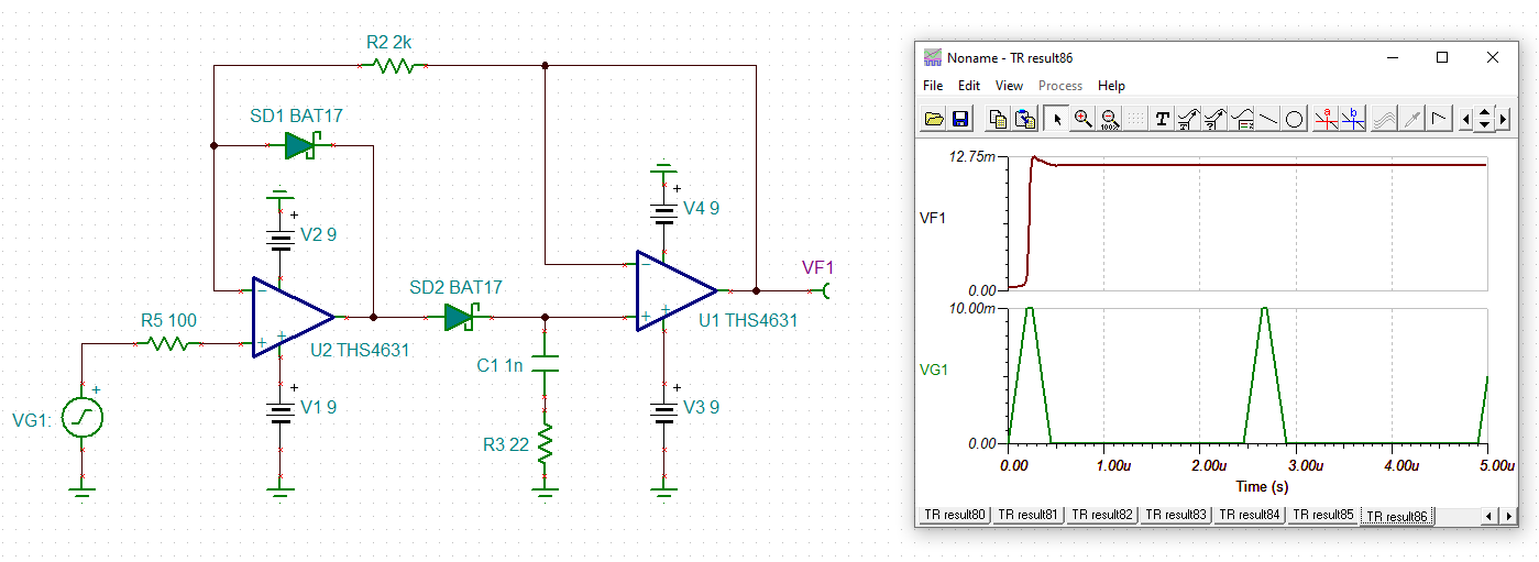
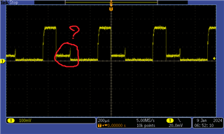
The output results are as shown below. I don't know why it appears in red, even though I cleared capacitor C1 with an analog switch. I need a solution to remove the part in that red circle.
Thanks,

Hai Lai

  • Hi Hai,

    Changing the capacitor values will have a slight difference but it doesn't seem to impact simulations the way the results you are sharing are being impacted. Is the drop at the output consistent to when the switch is turned on to discharge the capacitor? Also is there any info on the diodes you are using? Non-idealities might be the reason for this added offset.

    Best Regards,

    Ignacio 

  • Hi Ignacio,

    Thank for your reply.

    The diode that I am using is BAT17.

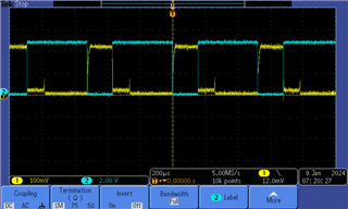
    The blue signal in the figure below is the capacitor discharge switch control signal.

    The switch that I am using is TMUX1101DCKR.

    Thanks,

    Lai Hai

  • Hi Lai,

    There is likely some kind of voltage still biasing somewhere in the network causing the output to have this offset. Is there a way you could probe the output of the first amplifier before the SD2 diode?

    Best Regards,

    Ignacio