This thread has been locked.

If you have a related question, please click the "Ask a related question" button in the top right corner. The newly created question will be automatically linked to this question.

INA226-Q1: INA226 for HV BMS Application

Part Number: INA226-Q1
Other Parts Discussed in Thread: INA181, INA226, INA238, INA228, SYSCONFIG

Hey,

Our HV BMS Application requires current measurements ranging from 0-2000A out of which 2000A is the peak current during overcurrent or short circuit scenario.

The continuous current will be not more than 300A.

Based on these requirements we had shortlisted the following system details using INA181(20V/V gain) variant:-

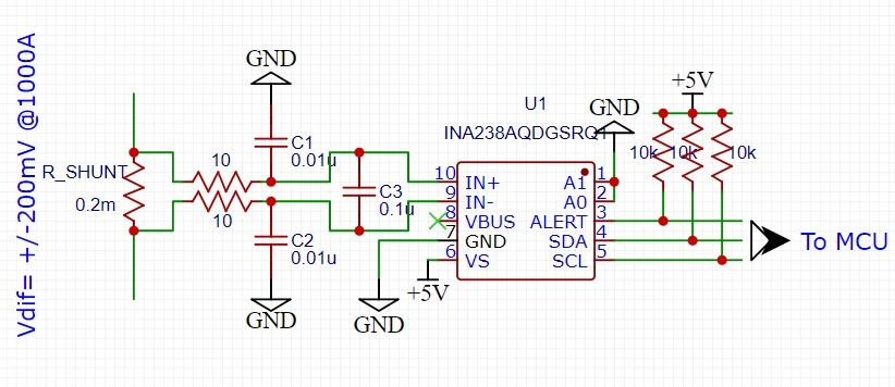
Rshunt = 0.2mohm with 100mV drop at 500A

Hence, at 300A continuous current the voltage drop across the Current Sense Amplifier input corresponds to 60mV Vdiff.

But, as we also need to detect over current or short circuit situation nearly at 2000A within few milliseconds the voltage drop across the current sense amplifier then will correspond to 400mV Vdiff which is comfortably within the common mode voltage range of the INA181 i.e., 26V.

Hence, as we need to select the INA181 with the lowest possible gain inorder to set up Vout below 5V for 2000A.

Considering we set the reference voltage of INA181 to 1V. The Charging current will swing between 0 to 1V Vout and Discharging current will swing between 1V to 5V Vout. 1V will translate to 0Amps.

Under these conditions we'll be able to measure a maximum continuous current of:

Vout=Vref+(Vdiff*gain)  

Vout=5V, Vref=1V, Gain=20

Vdiff=0.2V or 200mV is the max drop we'll be able to measure at Vout of 5V which corresponds to 1000A.

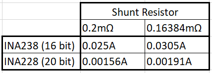
The resolution we can get using 12bit ADC of MCU is 5V/4096 = 1.2mV which translates to a step size of 6A which is too high for our application as we need the step size in mA for higher accuracy during coulomb count.

Hence, we were considering the INA226 for our application as it has 16bit ADC which can give us a step size 380mA.

Would like to know your thoughts if the INA226 will be suitable based on our conditions if not what is a better solution.

Thanks

  • Hello Mohammed,

    Thank you for using the TI forum. The INA226 input voltage range is actually only ±81.92 mV, not your desired 200mV, so it would not work well for this situation. The INA238 is a newer device that is similar in cost and accuracy to the INA226 (and also has a 16 bit ADC). The INA238 has an ADC range of ±163.84mV, which is still not as high as you wanted, but much better.

    You may also be interested in the INA228. This device has a 20 bit ADC, and also has an integrated Coulomb counter. This device also has a ±163.84mV input range. 

    For your setup, when using either the INA238 (16 bit) or the INA228 (20 bit), you would have 2 main options. You could leave the 0.2mΩ shunt resistor, but then only have a maximum measurable current of 819.2A, or you could lower your resister to whatever real value is closest to 0.16348mΩ to measure 1000A. With these options, your current LSB (rounded) would be:

    In order to measure with that accuracy/resolution, you would need to maximize the on-device conversion time and averaging. You can look at the ENOB table to get your affective number of noise free bits based on your specific conversion time and averaging settings. 

    Regards,

    Mitch

  • Understood Mitch. Thanks a lot for your feedback.

    1. Below is the schematic which we are going to deploy using INA238 as it has higher differential voltage compatibility compared to INA226.
    2. We're using a 0.2mohm shunt resistor to measure current in bidirectional mode for charge and discharge current. The discharge current based on Vdiff of 163mV can go max upto 819Amps measurable above which we'll go for the out of range condition alert to trigger a SC flag.
    3. Would like your view on this sample schematic for INA238 based on Bidirectional current sense requirement of 800 Amps discharge and 100Amp charge.
    4. Originally our requirement was to measure upto 2000A just for the sake of measuring SC current but it compromises on our LSB. Hence, we've settled for measuring max capability of the device at 819A for 0.2mohm and use out of range condition for determining short circuit.

    Thanks again for your valuable support.

  • Hello Mohammed,

    Generally your schematic looks good to me, however, I would recommend removing capacitors C1 and C2, as they can cause error when mismatched. Here is an e2e thread that discusses more about this: https://e2e.ti.com/support/amplifiers-group/amplifiers/f/amplifiers-forum/1221725/ina280-any-issue-if-the-input-common-mode-cap-value-is-mismatched

    Regards,

    Mitch

  • Thanks Mitch for your feedback.

    Also are my calculations for the current measurement using a 0.2mohm shunt correct as stated before?

    One more question i had was that the INA226, INA238 & INA228 are pin compatible right subject to the external circuit remaining same.

    Thanks again for your time.

    Regards

    Ibrahim

  • Hey Mohammed,

    You're welcome. Yes, your calculations are correct. 

    Yes, all 3 devices are pin compatible and do not require external circuitry changes. I will note that if you decide to run in High-Speed mode, then you'll need smaller pullup resistors. If changing between the devices, you would only need a software change. Fortunately, all 3 devices are available in SysConfig, which helps generate C code based on your desired configuration settings: https://dev.ti.com/sysconfig/index.html?product=ascstudio&device=Other

    Regards,

    Mitch