Is there a way to estimate how well this configuration works on a single supply (preferably 3V)? I'm looking for a sub $1 solution, is there a recommendation for a lower cost, general purpose op amp to use instead of OPA656/OPA727/THS4631?
This thread has been locked.
If you have a related question, please click the "Ask a related question" button in the top right corner. The newly created question will be automatically linked to this question.
Is there a way to estimate how well this configuration works on a single supply (preferably 3V)? I'm looking for a sub $1 solution, is there a recommendation for a lower cost, general purpose op amp to use instead of OPA656/OPA727/THS4631?
Hi Shimon,
Can you share with us some specifications such as:
Knowing these things will help us get a better starting point.
Best Regards,
Robert Clifton
Hi Robert,
The problem I'm trying to solve is almost identical to what is described here - https://e2e.ti.com/support/amplifiers-group/amplifiers/f/amplifiers-forum/940064/how-to-improve-the-accuracy-of-peak-detector-as-high-as-posssible
I cannot use the solution as is since I have only one supply (3.3V, may change to 5V if absolutely necessary) and the entire solution must be under $1 in BOM. I'm sure those two limitations will yield poorer performance, but would like to know if there is a way to estimate how poor. And, hope to get a recommendation on a lower cost op amp that will best fit.
Assuming a circuit running on 3.3V supply, the pulses (input signal) voltage range is ~0.5V to 3V, the maximum pulses rate is ~2Mpulses/sec and minimum rise/fall time is ~200ns
Thanks,
Shimon
Hi Shimon,
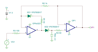
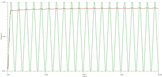
I think the best device we have in the general amplifiers portfolio is the OPA2323. We just released this device so the model isn't completed but might be good enough to figure out whether or not this will work in your application.
Accurate Peak Detector OPAx323.TSC
This isn't fully optimized. I just based it off of one of the circuits that they used in the thread to get a good idea of the op amp's capabilities.
Let me know your thoughts.
Best Regards,
Robert Clifton
Hi Robert,
Thanks. This very helpful. I'll use it as a starting point and optimize from there.
What is the purpose of the 50 Ohm resistors?
Thanks,
Shimon
Hi Shimon,
I usually recommend having an external resistor between the output of one op amp and the non-inverting input of another to act like an external current limiter.
In this schematic, I'm not entirely sure why the user originally put the 50ohm resistors in the schematic. Especially the one in the first stage feedback.
I also did forget to put the 20ohm resistor that was in the original schematic.
Best Regards,
Robert Clifton