This thread has been locked.

If you have a related question, please click the "Ask a related question" button in the top right corner. The newly created question will be automatically linked to this question.

INA199: Operation Question

Part Number: INA199

Hi,

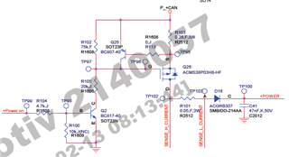
In the circuit below, SENSE_H_CURRENT and SENSE_L_CURRENT were connected to INA199 input, and a load of 500 ohms was connected to +POWER.

The P+CAN voltage is approximately 11.8V, the INA199 input voltage is 5V, and the REF is connected to the GND.

At this time, INA199 output is about 55mV.

Is the normal output voltage correct?

If you connect a load of 20 ohms to +POWER, it's about 1.2V output.

It looks like a normal output, is that correct?
  • Hello,

    Thank you for your post and looping us back in to help with your design :) 

    Can you probe the inputs to the amplifier and the output in your simulation or on your oscilloscope? I can give you a theoretical answer but I want to make sure that, when implemented in simulation or hardware, the INA199 is working properly.

    Can you also confirm that nothing from the previous post has changed? 

    Best Regards, 

    Joe