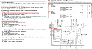
This thread has been locked.
If you have a related question, please click the "Ask a related question" button in the top right corner. The newly created question will be automatically linked to this question.
Hi,
We are developing a project by using AFE031 with Renesas MCU. I was facing problem in SPI communication. Once I write a register in AFE031 and again read from the register I couldn't get that expected write data. I receive the data as 255.
I was referred in many topics but my problem was not solved.
In our using MCU as can only transfer 8 bit data. So I Send the data as Split into two 8 bit data.
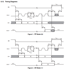
SPI configured as,
Mode: 1,1
Baudrate:9600 bps
Transfer direction :MSB
/*----------------------------
SPI WRITE
----------------------------/*
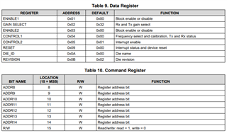
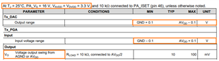
test_send_buf[1]=0x32; //Write Value
test_send_buf[0]=AFE_WRITE | AFE_GAIN_SELECT; // 0x00 | 0x02
/*----------------------------
SPI READ
----------------------------/*
test_send_buf[1]=0x00; //random Value for read
test_send_buf[0]=AFE_READ | AFE_GAIN_SELECT; // 0x80 | 0x02
Is anything I want to change in above config ?
Is necessary to change chip select (CS) pin state High to low in after every 16 bit data transfer complete ?
If there is any example application note is available with access registers please give us.
Thanks,
Hi Mani,
If there is any example application note is available with access registers please give us.
We have many customers who use 3rd party MCUs to communicate with AFE031 in their PLC controller product. It is likely that the SPI protocol is not configured properly.
SPI has two modes, see see the AFE031's datasheet, also the link below.
Please write a small program and test his read/write code via AFE031's registers via SPI protocol. I think that the SPI protocol is specific to TI and I recalled that SPI code implementation may be slightly different from others.
There are some differences between MCU and DSP processors to setup the SPI configurations. In the link below, there are some instructions in how to configure AFE031. Although this is specific to C2000 DSP processor, the overall procedure should be still correct for MCU processor.
https://www.ti.com/lit/an/sprac94d/sprac94d.pdf?ts=1705429676956
If you have other questions, please let us know.
Best,
Raymond
Hi Raymond Zhang1,
Thanks for your reply,
Yes, I was already saw those details. I was configured SPI as per the data sheet. But I am having a problem.
But there is a only different, which means datasheet have a 16 bit transfer SPI communication but I having a MCU can transfer 8 bit SPI.
1).Did you notice any configuration problem in my above details ?
2).Is we need to write a register before we read from a register , that is necessary or not?
3).can you tell what are the possibilities when read registers value as given 255.
Hi Mani,
AFE031's register is only supported in 16 bit word size (the registers are designed for 16 bit access only.). I am afraid that you have to configure the SPI communication in 16 bit. You have to find 16 bit MCU to communicate with the part.
If you have other questions, please let us know.
Best,
Raymond
Hi Raymond Zhang1,
Ok, I understand.
Can you tell about what are supported frequency levels are in SPI communication ?
I seen only Tx and Rx frequency levels in datasheet , can you tell about. or any frequency level is applicable for SPI communication ah ?
Hi Mani,
Can you tell about what are supported frequency levels are in SPI communication ?
The SPI needs to communicates > 1.5MHz, if you are using the onboard DAC feature.
If you are using PWM mode to send the GPIO signals to AFE031, then it does not require the higher speed SPI data rate.
If you have other questions, please let me know.
Best,
Raymond
Hi @Raymond Zhang1,
I have an a doubt
1. Is it necessary to give a voltage supply to PA_VS1 & PA_VS2 Pins whether I try to read in data registers and command registers ?
I found that details about to read registers in AFE031 like below for before start SPI to read data / command registers
1. SD Pin -> pulldown
2. DAC pin -> pulldown (Access only on command and data registers)
3. AVDD -> +3.3V
4. DVDD -> +3.3V
Is anything I missing or need to verify before start SPI communication to read the registers ?
Hi Mani,
1. Is it necessary to give a voltage supply to PA_VS1 & PA_VS2 Pins whether I try to read in data registers and command registers ?
Yes, it may be necessary. The PA_VS1/PA_VS2 establish the IC's internal bias voltage, as seen in the diagram below. It depends on which internal analog and/or digital block you are trying to access, the internal bias REF1 and REF2 should be present, which are used to bias other blocks inside of the IC, such as Control Register and other internal blocks. Otherwise, it may not have the proper bias voltage to work properly.
You do not need to apply the rated 26V to AFE031. If PA_VS1/PA_VS2 pins are connected to 10V to 16Vdc should do, I think that it should work. For instance, the following DAC signal depends on AVDD supply rail; the digital signal may depends on DVDD supply, rail, but the internal op amp and analog circuitries are powered by REF1 and REF2 bias voltage, which are not clearly specified. So it is necessary to connect to PA_VS1/PA_VS2 pins (no load is necessary, if you want to talk to the part).
If you have other questions, please let me know.
Best,
Raymond
Hi @Raymond Zhang1,
Thanks for your prompt response.
You are gave more information about AFE031 Registers Read and Write via SPI communication.
Now I have a availability problem of 16bit SPI communication MCU and PA supply circuit once it will be ready and I will check and update feedback to you.
Thanks,
Hi Mani,
Ok, if you have any questions, please let me know. We have many customers who are using their preferred MCU to interface with AFE031's SPI, register read/write and IC control. So the 3rd party MCU and hardware in communicating with the digital part of SPI are not the issues.
Best,
Raymond
Hi @Raymond Zhang1
Finally we did successfully Read and Write operation in Registers over SPI with 8 bit transfer SPI MCU.
I think if we have a lower bit transfer SPI MCU that is not a problem to communicate with higher SPI frame of peripheral.
what is the problem means ,
1. Our MCU SPI pins was interchange connect with AFE031 SPI pins so that why I received as value as 255.
2. If we can sent 2 no of 8 bit data but which one data send first is important ( I was face success when I sent MSB side 8 bit data first after I sent LSB side 8 bit data )
3. Need to give a supply of PA_supply , Once I will give a power to PA_supply pin Then only I get success
I noted the below details for to success read and write registers in AFE031
1. SD pin - LOW
2. DAC pin - LOW
3. INT pin - HIGH
4. Give a supply for DVDD , AVDD ,PA_supply pins
4. SPI configuration (below configuration was I did read and write registers)
* Mode: 1,1
* Frequency > 1.5 MHz
* Baudrate:9600 bps
* Transfer direction :MSB
* Single Transfer / Continuous Transfer mode
5. Before read a register, once write value as 0x14 in RESET register for soft reset for the very first
6. If We had a 8 bit SPI MCU , First send MSB side 8 bit data
ex. if we need to send data as 8900 means send like below
send_buf[0] = 89
send_buf[1] = 00
Finally Thanks for your support @ Raymond Zhang1