This thread has been locked.

If you have a related question, please click the "Ask a related question" button in the top right corner. The newly created question will be automatically linked to this question.

THS4531: output vs input

Part Number: THS4531
Other Parts Discussed in Thread: TINA-TI

is the +out=+in * gain - offset; regardless of what -in is doing?

for example with gain 2 and offset 2.5, +in 3.25, -in 1.75

is +out = 4 and -out = 1

or is +out = 3 and -out = 0

please and thank you for the help

  • we are seeing +out = 4 and -out = 1 making me think the two inputs act independently 

    yet

    when we apply a sin wave +3.25 max, 1.75min to +in and nothing to -in we get a wave on the output between ~ 4 and 3V. 

  • Hello Chris, 

       The common-mode voltage at -in and +in should be the same or else the circuit will not work as expected. Therefore, that is the reason you are seeing different calculations of the signals at +in and -in since there is a mismatch in the common mode voltages at these pins. 

      We have a precision lab video series on fully differential amplifiers and this video at this link (https://www.ti.com/video/series/precision-labs/ti-precision-labs-ti-pl-amps-fully-differential-amplifiers.html). This video covers common-mode voltage in combination of an offset in relation to differential voltage and output voltages. 

      Is your offset voltage set at +in or at the -in pin, would you be able to share the schematic?

    Thank you,

    Sima

  • Is there just a set of equations for VOUT+ and VOUT- which has the other pins as variables?

    The offset voltage is designed to be applied to the VOCM pin but currently we have only a .01uF capacitor on it (I believe this defaults the offset to 1/2 of the VS+ - VS-)

    VS+ = 5VDC 

    PD pin also connected to the 5VDC

    VS- = GND/return

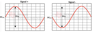
    I was confused by your comment that both inputs should be the same, but watching the video, it seems that they should be the same magnitude* but opposite polarity

    magnitude = difference between value and a common mode DCM

    this is referenced as golden rule #1

    this makes me think that I had the equation right:  +out=+in * gain - offset,  -out=-in * gain - offset

    BUT that the equation is only valid if rule #1 is followed

    equations when rule #1 is not followed are not available as output is no longer predictable 

    Is that correct?

  • Hello Chris,

      Sorry for the long delay on a response. For offset, I was referring to input offset which could be a common-mode DC voltage bias at either the +input or -input of the FDA. The output common-mode DC voltage is referred to as the Vocm voltage. When I was mentioning that the voltage should be the same, I meant the common-mode voltage at both the +input and -input to the FDA should be exactly the same in both polarity and magnitude. 

      The equations are a bit more involved, Vocm would be included at the nodal voltage directly at the positive and negative inputs of the FDA. I have drafted a PowerPoint showing how output voltage and differential output voltage differs when applying a offset or Vocm or both. Also, I show how you can have different input AC voltages but common-mode DC voltage should be the same at both inputs. 

     The equations and all plots are found in the FDA example PowerPoint. The zip-folder contains the snippets of the plots from Tina-TI and the simulation file I used. By the way, when plotting the figures, I accidently labeled Vin+ and Vin- incorrectly. I fixed this in the simulation file, but not in the PowerPoint plots. Let me know if you have any further questions; I hope this clears it up!

    FDA Example.pptx

    FDA Example Tina-TI Vin vs Vout.zip

    Thank you,

    Sima