This thread has been locked.
If you have a related question, please click the "Ask a related question" button in the top right corner. The newly created question will be automatically linked to this question.
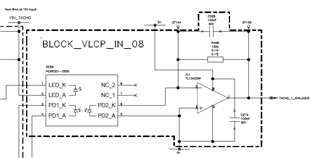
We will use TLV432 as amplifier for optocoupler secondary side.
In case the TLV432 doesn’t suppled, the primary side of optocoupler will still given energy that at the secondary side a current like 100µA is generated.
I need to know whether this 100µA is dangerous for TLV432 or not. In datasheet the maximum rating for input current is not given, only input voltage level is given.
Regards
Hi Qi,
Welcome to E2E!
Just to confirm, are you using the TLV342 in your application? You mention a "TLV432" multiple times so want to make sure which part you are using.
Also, do you have a schematic you can share so we can see how the amplifier is connected to the optocoupler?
Thank you!
Best Regards,
Ashley
Yes, it is the OPAMP TLV342, the two channel version of TLV341. The schematic is attached. The question is about, whether the current of 100µA from optocoupler OC69 could damage the OPAMP IC1 in TLV342, if TLV342 doesn't have supply voltage.
Thanks. Best Regards
Hi Qi,
Could you please re-upload your schematic? I do not see it in the thread. Is there anything connected between the optocoupler and the opamp?
Thanks!
Regards,
Ashley
Hi Qi,
Thank you for the schematic. 100uA on the inputs should be fine in this scenario if the op amp does not have a supply voltage.
Regards,
Ashley
Hallo, Ashley:
Thanks a lot for your answer. I could need a little more clarification.
Best regards.
Hi Qi,
I am an engineer from Texas Instruments as indicated by the "TI_" level on the top right side of my posts. Only TI employees can have "TI" in their level type.
Our forums are here to help answer questions with our parts however as stated in our terms of sale and datasheet, design and validation responsibility falls on the customer. We cannot give an official statement on customer designs.
I will need to validate in our lab what the input structures are. Please give me until end of day Wednesday (May 1) for my update.
Regards,
Ashley
Hallo,
Thanks for your answer.
Best Regard
Hi Qi,
I tested the TLV342 in lab and confirmed that there are internal diodes from inputs to negative supply rail (VEE), but not the positive supply rail (VCC). These diodes are generally what determine how much input current limit could damage the internal input structure.
For CMOS input devices, the current limit is 10mA, which is why I stated earlier that 100uA should be fine.
Regards,
Ashley
Hallo, Ashley:
Thanks a lot for your clarification. Let me summarize the facts.
Are the points correct.
Then an additional current beside my application, maybe for the future. What would be the acceptable input current from input to positive input, if for example the part used for comparator with positive feedback?
Regards
Hi Qi,
In TLV342, the clamp diode from input to negative supply is existing.
Correct, internal ESD diodes exists between the inputs and VEE
An input current from input to negative supply up to 10mA is actable.
Currents beyond 10mA will be capable of damaging the device. I would recommend staying below 1mA if possible.
In my application the input current up to 10µA is applied to negative input. Therefore, it is acceptable.
Correct, this will be acceptable for the device.
This device does not have diodes from input to input, therefore the comparator example is not a concern.
Thanks,
Jacob