This thread has been locked.

If you have a related question, please click the "Ask a related question" button in the top right corner. The newly created question will be automatically linked to this question.

OPA858: Self oscillation

Part Number: OPA858
Other Parts Discussed in Thread: OPA855

Dear All,

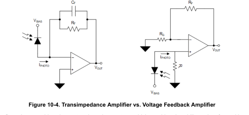
I'm using below circuit (op amp opa858) for photodetector input, but found the Vout have a high oscillation. 
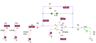
Simulation profile

Simulation result

which I use a current source as photo detector input, and add a dummy load R5 as CRO cable

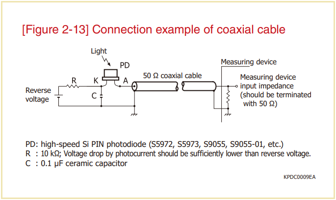
The circuit is for simulation only, on real measurement from CRO, the Vin I use a 50 ohm dummy load to confirm no input, but Vout waveform measure as (which Vout I use 50ohm cable to CRO directly)

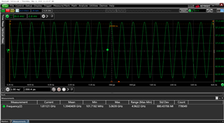
Can anyone give me some suggestion how to solve this "oscillation" ? And why simulation cannot reproduce this "oscillation" ?

  • Hello Vincent,

       A few design questions:

    • What will be your photodiode capacitance?
    • Also, what is R2 added in the simulation? It seems like you are using this as a Rg for a gain of -8V/V, but TIAs (current source) use a different type of configuration. 
    • Will your gain only be 400Ohms?
    • What is your frequency range or closed loop bandwidth (rise time of the input current)?

      Typically a TIA design would like this: 

      The input capacitance is internal to the photodiode. This value, closed loop bandwidth, and feedback or known as gain resistor will determine your feedback capacitance. I would suggest looking at pages 21-27 of the OPA855 datasheet which walks through the steps of designing a TIA. Also, we have a TIA calculator located in our FAQ page: e2e.ti.com/.../faq-h-frequently-asked-questions---high-speed-amplifiers

      Let me know if you have any questions on the content of the pages I listed of the TIA calculator.

    Thank you, 
    Sima

    • What will be your photodiode capacitance? 12pF
    • Also, what is R2 added in the simulation? It seems like you are using this as a Rg for a gain of -8V/V, but TIAs (current source) use a different type of configuration.  *The SImulation result above already include the R2 (50ohm). As the PD will connect to the opamp by 50ohm cable, so need to have a 50ohm matching
    • Will your gain only be 400Ohms? *yes
    • What is your frequency range or closed loop bandwidth (rise time of the input current)? *1GHz

    When I test, I add a 50ohm dummy load on the input SMA header and a 50ohm cable to CRO directly.

    Actually I'm confuse if the waveform I measure is  "Oscillation" or other caused, and anything missing on simulation which didn't show this oscillation.

  • Hello Vincent,

      I apologize for the very long delay on the reply. For very high speed TIA applications, we recommend the photodiode be as close as possible to the input of the amplifier to avoid parasitic such as inductance to cause instability to the overall circuit. Is it possible to place the photodiode without the cabling?

      The 50 ohm impedance matching would be done as shown in this e2e thread: https://e2e.ti.com/support/amplifiers-group/amplifiers/f/amplifiers-forum/1083284/opa320-photodiode-application-slang


      Which would be the second method of connection to amplifier shown in previous reply at the amplifier's non-inverting node. If you would like to read the difference, the e2e thread goes into more detail and section 10.3 in the OPA855 datasheet: https://www.ti.com/lit/ds/symlink/opa855.pdf

      For your design requirements, this is what would be the suggested values: 

      The photodiode capacitance is a major factor in the high GBP amplifier requirement of 30GHz to attain a Butterworth response. The OPA858 has a GBP of 5.5GHz which would give you a maximum of 427MHz for 65 degree phase margin, which possibly could be increased to closer to 500MHz for a stable circuit >45 degree phase margin. However, precise caution would have to be taken to layout especially keeping the diode as close as possible to amplifier's input. 

      The OPA855 has a gain bandwidth product of 8GHz which would increase closed loop TIA bandwidth to 515MHz. 

       Are you instead looking for optical network solutions which are dedicated TIAs used in optical receivers? 

    Thank you,

    Sima