This thread has been locked.

If you have a related question, please click the "Ask a related question" button in the top right corner. The newly created question will be automatically linked to this question.

OPA2192: OPA2192: input bias current caused by mux friendly input protection and lack of decoupling?

Part Number: OPA2192

Tool/software:

Hi,

this is a direct follow-up to my thread: "OPA2192: How does input bias current change close to supply rails?" I have found the root cause of my issues and wanted to share my findings. The original thread is locked. Therefore I have made this "related question".

First I reduced my circuit to this:
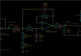
1. With no filter capacitors, passive pull-down at the input and no load at the output I measured 2.6mV at U13.7 and 3.3mV at U13.5. Good!

2. I then added C44 and measured 49.9mV at U13.7 and 50.4mV at U13.5. There is a DC current flowing out of the positive input terminal of the opamp at (50.4mV/(12k+36k))=1.05uA

3. I then implemented the same changes on a different board and the strange offset current was not present on that board!

4. I then started to add all the other changes to different functions on board nr 2 and the offset problem eventually also was visible on that board.

Long story short:

The root cause was found to be a decoupling cap that was removed to cost-optimize a different function on the board. When I added that capacitor back on the problematic board, the complete circuit including both amplifiers and filter caps is able to drive the ADC down to 6.2mV with all components mounted. Please note that we always had a 220nF capacitor close to the package for decoupling. The missing capacitor causing the issue was a 4.7uF capacitor placed somewhere along the track to the opamp.

My understanding of the problem (Speculation):

This opamp has a "mux-friendly" input protection that is described in SBOT040C Application Brief MUX-Friendly, Precision Operational Amplifiers:
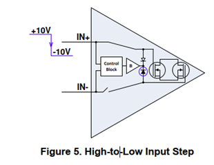
I think the increased ripple voltage caused by my missing decoupling capacitor is misinterpreted by the control block as "input steps". This is (maybe?) causing the  analog switches to toggle rapidly and you get some sort of "switched capacitor" behavior with a net DC current through the positive terminal. I do feel that the problem is under control now but it would be nice to have a comment from you to improve my understanding.

BR,

Øyvin Eikeland

  • Hi Oyvin, 

    Art is out of office on business travel. For this reason I am responding here to the follow up. Let me know if I am misinterpreting the question. 

    My understanding of the issue is there is switching voltage steps on the input of the device. Without the decoupling capacitor you are seeing an unexpected error voltage reflected on the output of the device. This error goes away when you use a decoupling capacitor. Is this correct?

    This would make sense since the decoupling capacitor is acting as a charge reservoir to the device during large steps in a short period of time. Any inductance on the PCB between the power supply connection and the VCC/VEE pins of the OPA will limit the amount of current to the device during transient and switching events. There is a current demand internally during these events and the decoupling capacitor will help provide this current. Without the decoupling capacitor it is difficult to identify what is going on internally. We always recommend to add decoupling capacitors as close to the device supply pins as possible. Without decoupling capacitors unexpected device behavior can occur if the device is starved for current due to inductance.

    I hope my interpretation was correct and the input was helpful. Let me know if we can be of further assistance. 

    Best Regards, 

    Chris Featherstone

  • Hi,

    the issue is not about switching voltage steps at the input. I do not know if I should ask you to go back the complete thread I am referring to. I will try to make a recap here:

    1. We are using the OPA2192 to feed an ADC. The opamp is powered by +15V to GND. The "problem" is that the opamp is not able to drive the output as close to GND as I think it should according to the datasheet.

    2. After some experimenting I found that the problem is only present when the capacitor at the positive input terminal of the opamp is mounted.

    3. The simplified circuit shown in my previous posting was used to demonstrate this. I removed R56, R15, C43 and C44. The opamp is connected as a unity gain voltage follower with no load and the positive input terminal is driven by 48kohm connected to GND. The opamp is powered by GND and +15V. Configured like this, I get 2.6mV at the output. This is in line with the datasheet. If I then simply add C44=100pF, I get  49.9mV at the output and 50.4mV at the positive input terminal. This is strange and this is the issue I am trying to get at. There is actually a DC current flowing out of the positive input terminal that is way higher than it should be.

    4. If I then add the decoupling capacitor of 4.7uF to the track about 30mm away from the opamp, the output changes back to 2.6mV. Note that there is also a 220nF decoupling capacitor sitting right next to the opamp.

    5. I have a theory that the increased ripple voltage caused by my missing decoupling capacitor (4.7uF) is misinterpreted by the control block in the input protection of the opamp as "input steps". This is (maybe?) causing the  analog switches to toggle rapidly and you get some sort of "switched capacitor" behavior with a net DC current through the positive terminal.

    6. I do feel that the problem is under control now but it would be nice to have a comment from you to improve my understanding.

  • Your explanation is plausible. But an unstable power supply could affect all parts of the chip, so I doubt that a complete analysis is possible, or that TI would publish it here.

  • Hello,

    Do you have any information on how much supply ripple or the frequency of the supply ripple?  Is it a DC/DC converter?  Agreed that if the ripple is high enough on a supply, then that could introduce many different problems.  But, it would surprise me if this was a problem with 10-20 mV of ripple.

    Did I miss this angle - is the input voltage in this test case a DC signal, or does it also have AC voltage?

    Regards,
    Mike