
- Ask a related questionWhat is a related question?A related question is a question created from another question. When the related question is created, it will be automatically linked to the original question.
Tool/software:
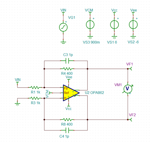
I want to use opa862 as a differential adc input driver. My signal is in the range of 0-5V and the ADC input range is 0-2V.
So I conducted a Tina simulation using opa862 as an inverting amplifier.
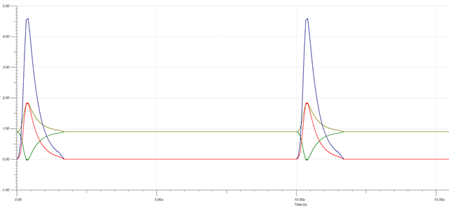
The results of the simulations are satisfactory; however, they are implemented in real hardware and oscillation occurs in the output pins during the operation of the corresponding circuit.
I wonder if oppa862 doesn't fit my application.
I'm asking for someone's help with the difference between simulation and actual hardware operation.The symptoms are the same even on bare boards.


