RCV420: conversion for multiple range

Part Number: RCV420
Other Parts Discussed in Thread: TINA-TI

Tool/software:

Dear Team,

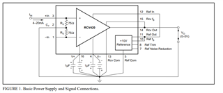
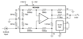
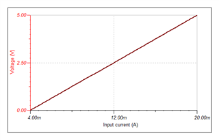
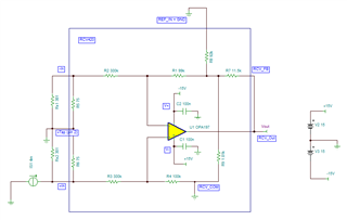
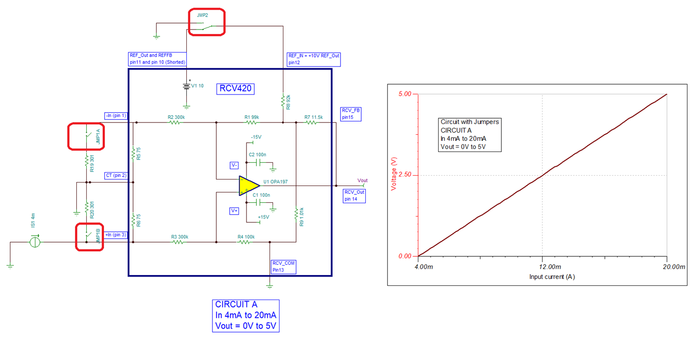
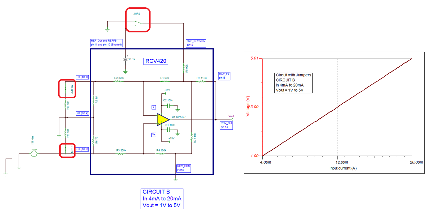
How Can I Achieve 0 - 5v and 1 - 5v for the input current of 4 - 20mA using jumper for bypass one of this ?

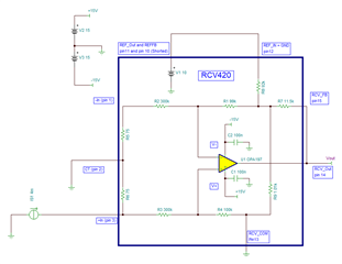
Could you suggest or provide the TINA simulation for this ?

Hoping to hear from you soon.

Thanks & Regards,
Mr. Prajwal P. Bhuse

  • Hi Prajwal,

    The RCV420 data sheet shows examples of these circuits.

    Circuit A.  Please review the RCV420 datasheet of Figure 1, this circuit provides an output of 0-5V for a 4-20mA input meeting one of your circuit requirements.

    Circuit B.  Similarly, please review the circuit of RCV420 data sheet Figure 15.

    By inspection, the circuit of Figure 15 can easily be modified: instead of sinking current of pin 1 (-IN); modify the circuit to inject the 4-20mA current into pin 3 (+IN). This circuit will provide an output of +1V to +5V for a 4-20mA input current meeting the second project requirement. 

    See the modified figure below, to meet the +1V to +5V output for an input current of 4 - 20mA:


    Unfortunately, the RCV420 is a legacy device from 1988 (36 years old); hence we do not offer an official RCV420 SPICE model. Nevertheless, you could use an op amp and resistors to create an idealized model to verify the ideal transfer function of the circuits above. See the TINA simulation for both circuits below.

    Circuit A: 

    Tina File Circuit A:

    RCV420_CircuitA_July_12_24.TSC

    Circuit B implemented in TINA-TI below, this circuit will provide an output of +1V to +5V for a 4-20mA input:

    Tina File Circuit B:

    RCV420_CircuitB_July_12_24.TSC

    Thank you and Regards,

    Luis

  • Dear Team,

    Is there any updates on our previous discussion ?

    Eagerly waiting for your reply

  • HI Prajwal,

    Which discussion are you referring to?  The RCV420 circuits to achieve 0 - 5v and 1 - 5v for the input current of 4 - 20mA and the corresponding simulations are above. You should be able to easily implement these on your PCB board design by using optional jumpers.

    Please review.

    Regards,

    Luis

  • Hello Luis.

    Thanks for your reply. as you've shared two separate schematics for it but what will be my jumper settings/configuration so i can achieve both ranges i.e. 0-5v and 1-5v in single circuit ?

    how can i place jumper so the design will be useful for both 0-5v and 1-5v ?

    Kindly check this and let me know.

  • Hello Prajwal,

    Looking at the diagrams on the previous post, it is possible to implement the circuits. Here is a simulation file that provides optional jumpers on the same schematic to configure the circuit. In the simulation file, the jumpers are represented with manual switches. 

    Circuit A, provides 0V to +5V for 4mA to 20mA input.

    JMP1A and JMP1B are OPEN. They disconnect the external 301Ω resistors from the RCV420 Inputs.

    JMP2 shunts pin 12 (REF In) to pin 11, pin10 (REF Out and REF fb)

    Circuit B provides 1V to +5V for 4mA to 20mA input.

    JMP1A and JMP1B are CLOSED. They connect the external 301Ω resistors from the RCV420 Inputs (pin1, pin 3) to CT (pin 2).

    JMP2 shunts pin 12 (REF In) to ground.


    Attached is the TINA-TI file with jumpers (manual switches).  

    RCV420_CirctuitA and B_jumpers.TSC

    Hope this helps,

    Regards,

    Luis

  • Hello Luis,

    Thanks for your reply. it seems like my problem was problem.

    will check this and get back to you for any further queries.

    Thanks for your support.

    Thanks and Regards,

    Mr. Prajwal P. Bhuse