This thread has been locked.
If you have a related question, please click the "Ask a related question" button in the top right corner. The newly created question will be automatically linked to this question.
Tool/software:
Hi,
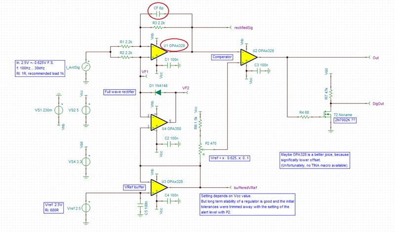
just tried to design a current sensor monitor. I need to get an alarm, if the bidirectional current exeeds the allowed margin. Pulses were ok, rest could done in the FPGA.
To reduce the need of monitoring two levels I use a full wave rectifier. The level is trimmed manually. (Scientific instrument, no mass production).
Any suggestens to make this circuit better?
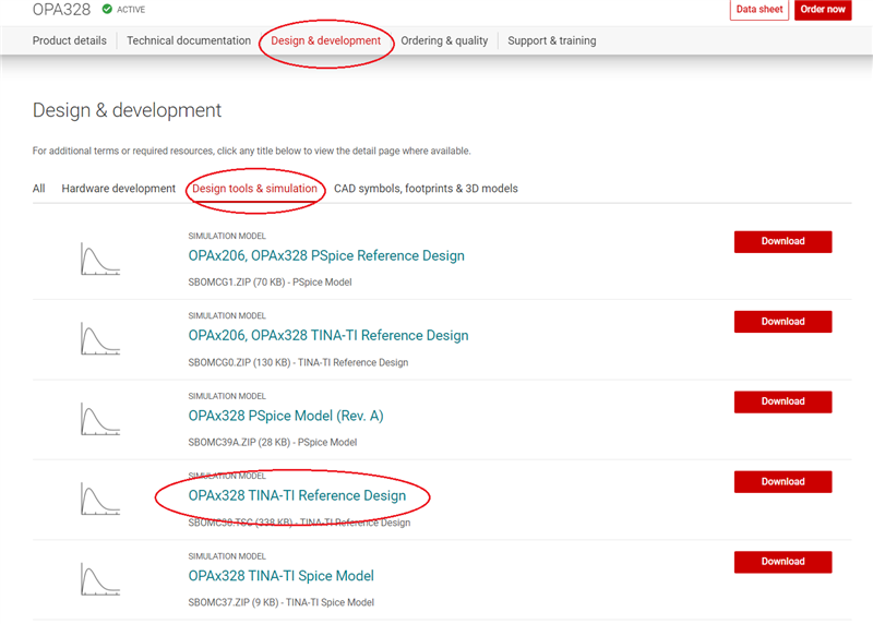
Is a TINA model for the OP328 available, because this could be the better choice than the OPA350?
Thanks for revieewing the circuit.
With beest regards
Gerhard
H Gerhard,
Your circuit looks good. OPA328 model is available - I included it in the simulation below. I also added a compensation cap across the feedback resistor.
Hi Marek,
thanks a lot.
But you leave one OPA350 (the amp with the diode in the feedback). I want to reduce the amount of different parts and so I set this amp also to OPA328, but ... simulation hangs.
Where can I find the OPA 328 TINA model, or more general, where can I find other missing models? Looked at the product page, nothing to find.
With best regards
Gerhard
Hi Gerhard,
The macro-models may be found under each product folder:
Yes, there is a convergence issue with one of the OPA328 - I reported the problem to our modeling team. Thus, in the meantime, please use the circuit as I sent it to you. After the issue is resolved, in the final schematic you will on use only OPA328.
.. oh my god. I looked there but lokked for TINA or SPICE, not for 'Reference design' ... sorry.
With beest regards
Gerhard
Thanks for helping.
Hi Marek,
I also need a symmetrical (DC free) output, they decide to use a pro audio recorder to record this signal. As I have the THS210 at hand, I used it.
To get things simpler I removed the negative bias circuitry, cause the OPA328 should be RR.
Now I get convergence problems again (told me D1). Any idea?
Is there something to simplify?
With best regards
Gerhard
Hi Gerhard,
Sometimes the default parameters need to be change to help simulator to converge. Please change the Shunt conductance from zero to 1p - see below.
By doing so the simulator found the convergence point and the transient simulation successfully completed - see below.