This thread has been locked.

If you have a related question, please click the "Ask a related question" button in the top right corner. The newly created question will be automatically linked to this question.

OPA2210: [Cont] CMRR for a Instrumentation Front End

Part Number: OPA2210
Other Parts Discussed in Thread: OPA2140, INA851, OPA2828, PGA855, OPA140

Tool/software:

The previous thread was locked.

I stacked another resistor network on OPA2140 feedback, and the CMRR improved. The unit is in uV/V
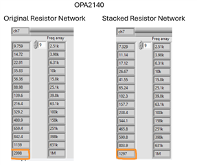
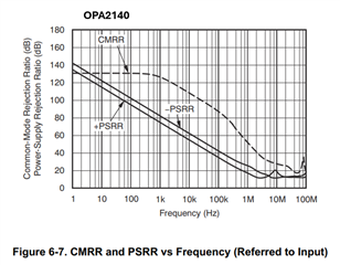
While this experiment shows the feedback network does affect the CMRR, the result is still off from the datasheet figure of ~32uV/V (-90dB) at 100kHz
Also, not every channel is this bad:
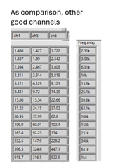
 These channels are with original resistor network values.

So I feel like this could be a device to device variation, just that it has quite a big spread.

Appreciate if the team can provide more insights. 

  • Hao,

    1. I read through the previous post and will help you with this question.
    2. When I look through your most recent data it appears that you get good DC CMRR.  Can you confirm?
    3. Assuming the DC CMRR is good, this means that your resistor network is ok.  Mismatch in the resistors will impact DC CMRR.
    4. Assuming the problem is only AC CMRR there are two factors that impact this parameter:
      1. The Op Amp CMRR across frequency.
      2. External capacitors in your discrete INA.
    5. I think the problem is likely the external capacitors in your discrete INA.  Here are some comments on this:
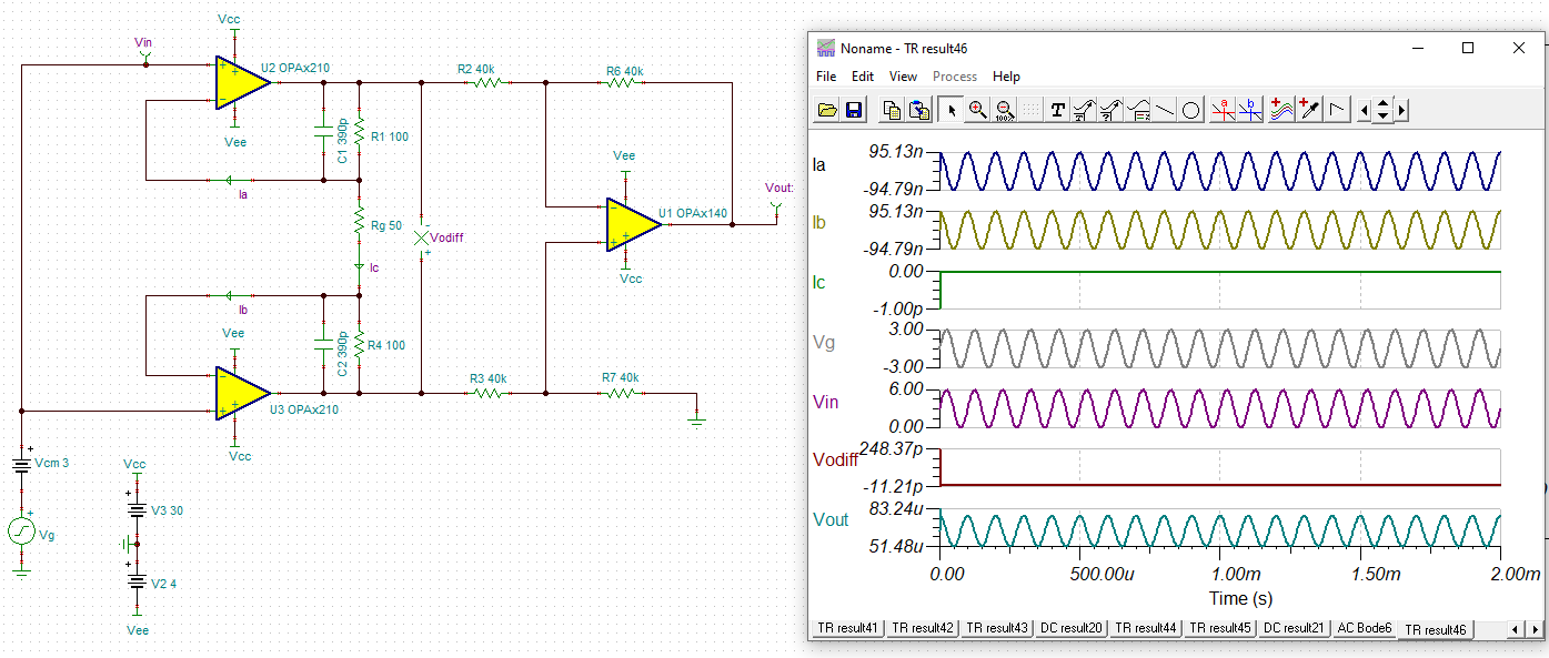
      1.  Referring back to the original post (see image below).  Capacitors such as C1 and C2 will have tolerance.  Tolerance errors in these capacitors will translate a common mode signal into a differential signal.  This will degrade AC CMRR but not DC CMRR.  Normally capacitors will have tolerances on the order of 5% to 20%.  This would easily degrade AC CMRR.
      2. This same kind of issue can occur because of an external filter (at the input of the INA).  In general, CMRR issues occur because of mismatch in components.  DC CMRR will be due to mismatch in the resistors, and AC CMRR is due to a mismatch in capacitors.  For circuits with well matched capacitors, the op amp CMRR can eventually show us as an issue.
    6. In general, it is difficult to get the excellent CMRR of an monolithic INA (e.g. INA851), with a discrete version.  There are many other advantages to the monolithic INA.  Let me know is you want to discuss monolithic INA options.

    I hope I didn't miss an key point from the previous post, and I hope this information is helpful to you.

  • THanks for the reply Art.

    • When I look through your most recent data it appears that you get good DC CMRR.  Can you confirm?

    Yes, DC CMRR is good.

    I think the problem is likely the external capacitors in your discrete INA.  Here are some comments on this

    I would agree it's likely some capacitance somewhere, but I am suspecting it's the op amp more, here's my thoughts:

    -I didn't specify C1 and C2 before, but they are pretty tight-controlled capacitors, 3.9pF±0.1pF NP0. So they are well matched.

    -I swapped ch5 and ch7 op amp before stacking the resistor network, and I found that the CMRR performance "follows" the particular op amp, and not the channel (indicating channel layout/ feedback is okay)

    it is difficult to get the excellent CMRR of an monolithic INA

    I totally agree. Unfortunately, I am doing this because currently available INA does not meet my specifications completely. But I am open if you have more suggestions to improve the performance.

  • Hao,

    When the problem follows the device, it does generally indicate that the issue is related to the device.  However, CMRR across frequency is generally a parameter that is not expected to very by large amounts, so we really don't expect the op amp to be the issue.  Nevertheless, once we eliminate other possibilities we will look at the op-amp CMRR. The previous thread has a lot of detail and I want to make absolutely sure that i understand your current situation.  With that in mind, can you please answer the following questions:

    1. Show the schematic.  Ideally I would like to see the entire signal chain.   
    2. How do you test CMRR?  Signal input connections/measurements, signal output connections/measurements, and equation.
    3. What are the key specifications that you could not achieve with one of the monolithic INA that you can achieve with the discrete?  Why did you choose OPA2140 for your discrete INA? 
    4. Although I am skeptical that the OPA2140 has an AC CMRR issue, let us assume this is the case.  What is the key specification in OPA2140 that you require?   Are there alternative amplifiers?
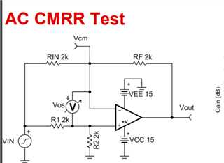
    5. Attached is a PDF that describes the typical test method for CMRR.  Could you modify your circuit to run this test?  This would show the CMRR of the op amp and not the INA.  1231-CMRR-ac-and-dc.pdf

    Best regards,

    Art Kay

  • Show the schematic.  Ideally I would like to see the entire signal chain.   

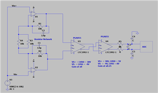
    I made a simplified schematic, hopefully it shows the idea:

    How do you test CMRR?  Signal input connections/measurements, signal output connections/measurements, and equation.

    As shown in the schematic, to test CMRR, I short the two inputs, and inject sine waves with 6Vpp, 3V offset, and sweep the frequencies. Data acquired by the ADCs are processed to find the amplitude of the given frequencies. CMRR is AmpltiudeMeasured(Vpp)/Gain (5*8*0.25 = 10)/6Vpp

    What are the key specifications that you could not achieve with one of the monolithic INA that you can achieve with the discrete?  Why did you choose OPA2140 for your discrete INA? 

    Offset drift <1uV/degC,

    Gain error <0.1% (the INA851 Gain error at Gain of 10 is 0.2%  ),

    CMRR of 80dB at 100kHz,

    slew rate of ~20V/us

    What is the key specification in OPA2140 that you require?   Are there alternative amplifiers?

    It matched the specs stated above. We are also looking at OPA2828, although the power consumption is a bit too high for our liking, we would be evaluating that next. 

    Could you modify your circuit to run this test?  This would show the CMRR of the op amp and not the INA.

    Thanks for the document. You mean this circuit right? 

    Unfortunately our board right now is not suitable for this change, right now all the networks are configured as the schematic above.

     Thank you Art Kay for your thoughtful response!

  • Hao,

    Thanks for all the information.  This really helps clarify the situation. 

    Below is my analysis of the circuit:

    1. When a common mode input signal is applied to the input stage (U1 & U2), the two amplifiers will each output a signal that has almost no dependency on CMRR.  The output of each amplifier is approximately equal to Vcm.  This is a first order approximation, but any difference due to Vcm, Aol, PSRR, or other error sources would be very small compared to the output signal.  Furthermore, if U1 and U2 match each other the errors would be equal in the two outputs. See power point below for simulation images.
    2. The two output signals from U1 and U2 are applied to the input of U3.  These signals are a common mode input to U3 since they are equal to each other.  The CMRR of U3 would determine how this signal is rejected.  
    3. The mismatch in the resistors in the first stage would translate the common mode signal into a differential signal.  This mismatch would constitute a DC CMRR error as the remainder of the stages would amplify the differential signal.  
    4. The mismatch in feedback capacitors would translate the common mode signal into a differential signal also.  This would degrade the system AC CMRR, but the cutoff frequency for this effect would be quite high and would not likely impact AC CMRR.
    5. The CMRR error of U1 and U2 would cause very small errors in the two outputs and those errors would be comparable assuming CMRR of the two amplifiers match.  I would expect other error sources to introduce errors of similar magnitude.  In other words,  CMRR is a secondary effect on the input stage.
    6. If you assume the discrete components are ideal, the CMRR of the PGA855 would dominate.  This is because each output of the fist stage is approximately equal to Vcm.  If the input stage components are not ideal this could set CMRR, but I would expect to see the error at DC as well as AC.  
    7. The AC CMRR specification for PGA855 for 100kHz is about 95dB in a gain of 8V/V.  This number is good, so I would expect good overall CMRR at 100kHz.

    Conclusion:

    In the analysis above I did not find the source of the system CMRR limit.  However, I do believe that the AC and DC CMRR of U1 and U2 should not have much impact on the system CMRR.  Mismatch of the resistors and capacitors on the first stage could cause system CMRR issues.   The first stage common mode output is equal to the common mode input, thus the second stage (U3), will have the common mode applied to it and it's CMRR should dominate the system.  The output of the second stage is applied to the third stage.  I am not sure why you have a third stage.  Couldn't you just use one PGA855? 

    Note: CMRR is really a small signal condition.  When you put Vcm = 6V, this may be the problem with the measurement.  Signals greater than 100mV cause slew rate to be a concern (i.e. large signal).  This can cause errors in your result. 

    Also, the fact that CMRR changed when you stacked the resistor network leads me back to the resistor being the issue.

    Next Actions:

    I suggest trying the OPA2828 as well as multiple OPA2140.  Do a thorough PCB clean between trials.  You should also bake out any moisture resulting from the PCB clean.  I do not think the issue is related to CMRR of the op amp, but maybe some other op amp issue is causing this problem.  You may consider using only one PGA855.  Look at the PDF below.  This will illustrate the points above.  

    I know this is a lot of info.  I hope it helps you to narrow down the issue and resolve it.  The main point of this post is that I don't think CMRR of the op amp is the problem.

    CMRR for discrete INA and PGA855.pdf

    Best regards, Art

  • Thanks for the reply Art.

    Mismatch of the resistors and capacitors on the first stage could cause system CMRR issues.

    This is still one of our hypotheses. And the observation that stacking the resistor network improved the CMRR by nearly half seems to indicate that something is interacting with the feedback resistance. 

    We are thinking could it be the input capacitances of the op amps? Maybe on a single amplifier, the capacitances between pins are matched, so the CMRR is great, but between amplifiers, the capacitances are not equal, which is why reducing the feedback resistance improves the CMRR. 

    And since this "parameter" varies from amplifier to amplifier, this could also explain why the "bad" channel would follow the op amps.

    We tried to simulate this, and it seems the capacitance needs to vary up to 30% for us to see this degradation of CMRR of 2140. 

    What is your thought on this, Art?

    Do a thorough PCB clean between trials

    Yes, contamination would affect this sensitive measurement, so we cleaned the board after the reworks.

    I suggest trying the OPA2828 as well as multiple OPA2140.

    We have another board coming in soon with the OPA2828, we are very interested to evaluate the performance of the amplifiers in this application.

    -Hao Jie

  • Hao,

    1. I think you are correct that a mismatch in capacitance on the op amp input may translate into a mismatch of the two amplifiers output which would show up as degraded CMRR for the system.  However, on a dual amplifier both amplifiers are on the same die so the capacitors on each channel should match well.  Furthermore, these capacitances are small so I would only expect effects to show up at high frequencies.  Of course, the PCB layout could create parasitic capacitance that is not matched if one trace is much larger than another.
    2. One possibility we have not considered is damage to he device.  It is always possible during prototyping that you could damage the device which would lead to degradation of multiple specifications.
    3. On comment I made on the last post is that CMRR is a small signal effect.  There was a lot of comments in the last post, so this would be easy to overlook.  By small-signal I mean signals less than 100mV.  The small-signal requirement is to avoid slewing the circuit.  For example, the normal closed loop bandwidth of an op amp is a small signal bandwidth.  When applying a 6V signal, you may introduce errors related to large-signal effects.  Can you do the test again with a 100mV (or less) peak-to-peak signal?  

    At this point I suggest you continue with your experiments for a while.  Try different op amps for U1 and U2.  Try to completely remove the feedback capacitors.  Try to reduce your common mode signal to 100mV or less.  Check out the new board to confirm that the two systems have similar performance.  Hopefully, in the process of doing this you find something we overlooked.  If not, let's reconnect in the future to discuss your findings.  I don't have any further suggestions at this point.

    Best regards, Art

  • Art,

    Do you know how TI measures the common-mode and differential capacitance? Is it possible to measure a few samples of the op-amp? And also if it's possible can you share the methodology to do the measurement? 

    I'll make some new measurements on new boards coming in very soon. I'll try a smaller signal measurement to see if there is any difference.

    Thanks again for the support so far.

  • Hao, 

    I believe this is generally extracted from the design data base (I will double check).  In some cases it is measured.  You could measure the common mode capacitance by placing a large resistor in series with the input of the op amp in a buffer configuration, and sweep frequency looking for the 3dB point.  Choose the resistor so that the cutoff due to input capacitance is a lower frequency than the amplifiers closed loop bandwidth ( 1/(2*pi*Ccm*Rsource) << BWCL).  You can then use the measured bandwidth to calculate Ccm.

    However, I think you are looking in the wrong area for AC CMRR degradation.  Ccm for OPA140 is 7pF.  Normally the tolerance of this capacitance is on the order of 20%.  The zero frequency due to this capacitance is 1/(2pi*0.5Rg*Ccm) = 5.6MHz.  You are seeing effects in the 100kHz range.  Even if you assume that the capacitance is significantly different from the specified value you aren't going to see effects at 100kHz.  Furthermore, if you do a survey of op amps, you will find that input capacitance is less than 10pF for the vast majority of amplifier. 

    Best regards, Art