- Ask a related questionWhat is a related question?A related question is a question created from another question. When the related question is created, it will be automatically linked to the original question.
Tool/software:
Hello TI engineer team,
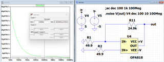
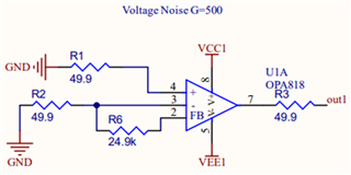
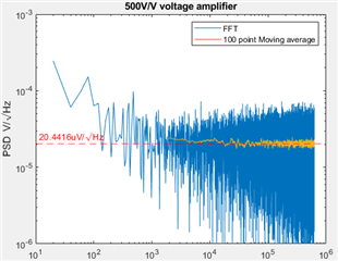
I designed a charge amplifier with OPA818 but the noise measurement was found about 20 times higher than simulation results. So, I designed the following voltage amplifier as a test circuit dedicated to check the Op-Amp built-in voltage noise level. The input of this 500x voltage amplifier is short to ground in order to measure only the noise.
A straight forward calculation is Vn = 2.2nV/sqrt(Hz) * 500 = 1.1uV/sqrt(Hz). Accounting for current noise and thermal noise, simulation gives 1.32uV/sqrt(Hz) at 100kHz. However, the measurement is 20.4uV/sqrt(Hz), 15 times higher.
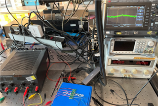
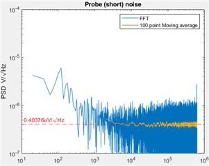
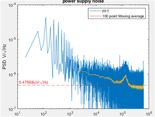
Regarding test equipment, I used Keysight DSOX1202G oscilloscope with a noise floor of 0.4uV/sqrt(Hz). OPA818 is powered by +5V and -5V. The voltage source has a noise floor of <1uV/sqrt(Hz), measured on PCB after bypass capacitors. All measurement used ground spring.
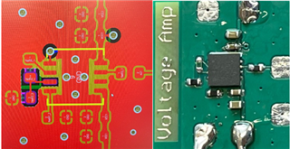
Regarding PCB assembly, proper ESD protection was used. The reflow temperature is well below 250C because of low temperature solder (127C melting temp). I have tried with and without IPA cleaning, the noise measurement results were same.
Regarding IC supplies, I bought from two different suppliers, Mouser and Digikey. They both gave consistently high noise results.
Please educate me if my design, assembly or test setup would cause the excessive noise. I would appreciate any help and advice. Otherwise, I have to suspect the OPA818 ICs do not meet the datasheet specification. Or perhaps this fabrication batch went wrong.
P.S. I did not buy and test the OPA818 evaluation board is because my current measurement equipment has a higher noise floor than that 7V/V eval board.