- Ask a related questionWhat is a related question?A related question is a question created from another question. When the related question is created, it will be automatically linked to the original question.
Tool/software:
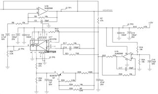
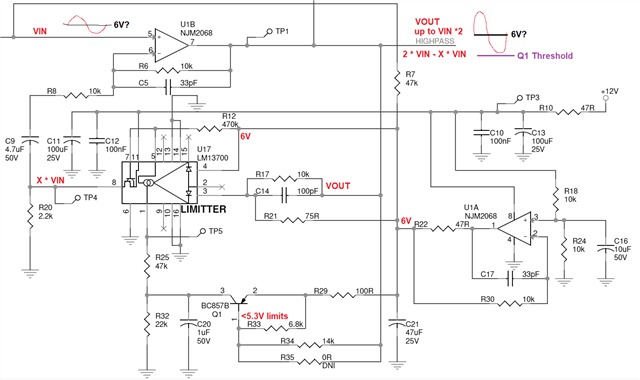
Hi Team,
I have come across a limiter circuit in a audio amplifier circuit. The circuit is not functioning when we overdrive the signal.I am attaching a schematic here. Could you explain how this circuit works? am not getting proper output