OPA387: Use as an integrator Is Not Working As Expected

Part Number: OPA387
Other Parts Discussed in Thread: TLV9061, TINA-TI, INA826, OPA392, OPA333, TLV9062

Tool/software:

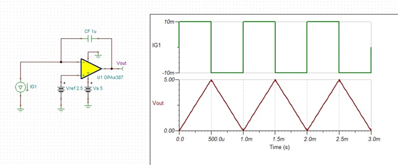
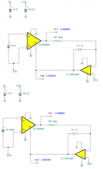
I'm using the OPA387 as an integrator.  It's part of a servo loop controlling the DC output of another amplifier. The power rails are +5 and GND. The non-inverting terminal is fixed at 2.5V. It correctly integrates up, but not down. In one example, it correctly integrated up to 4.15V. In the negative direction, it seems to have run out of room where it should have integrated down to 0.87V, but instead it stopped at 1.8V. Not even close. The + terminal sits at 2.5V and the - terminal is at 2.7V...so it's no longer running linear.

I replaced the OPA387 with TLV9061, and the integrator works as designed. There are some slight differences in the chip, but I don't see why the TLV9061 works and the OPA387 does not. Could it have something to do with amount of capacitance in the feedback loop? Maybe something else?

Please advise, thanks!

  • Gene,

    A picture is worth thousand words - please attached schematic of your application showing values of the components used including feedback capacitance and load. 

    The OPA387 integrator seems to properly simulate its basic function.  Please modified the attached Tina-TI schematic showing details of you application.

    You may download a free copy of Tina-TI simulator by clicking on the following link: https://www.ti.com/tool/TINA-TI

    OPA387 integrator.TSC

  • This looks nice, but surely does not work that way on my bench. The TLV9061 works just like this, however.

  • Have you received my schematic snippet? I sent it via reply to the email. Maybe it did not get to you, and I should post it here?

  • No, I have no received your schematic - you may not replay by email.  Please reply here and use Insert-> image/file to attached Tina schematic. 

  • Gene,

    With this kind of issues, a devil is in the details especially when it comes to circuit DC biasing.  However, with almost all your schematic nodes floating in outer space, there is not much I can do here, other than to say to check the linearity of INA826 using our Vcm vs Vout calculator - see below.

    You may download a free version of TI Analog Engineer's Calculator by clicking on a following link: https://www.ti.com/tool/ANALOG-ENGINEER-CALC

  • I didn't want to show you the stuff around it....some of that is experimental and is not populated. I can draw you a simplified schematic. At some level, I can't show you proprietary stuff in this open forum (it's nothing Earth shattering, just company private). That's partly why I chopped off the other stuff that really isn't connected.

    Keep in mind, that it runs quite nicely with the TLV9061. The noise is higher on the TLV9061, but at least it integrates properly.

    Also, the DC servo works fine with the OPA387 as long as there is little to no DC offset at the input to the INA826.

    Yes, I'm right in the sweet spot on the input of the INA826. But this is all besides the point, I think. Go back to the original question....the OPA387 would not integrate down enough from 2.5V. I'm not seeing how the rest of the circuit matters. In the static case, there's a DC voltage on the non-inverting terminal and a pretty DC-ish signal on the inverting terminal. The OPA387 needed to integrate down to around 0.8V in order to keep closed-loop, but it only got down to around 1.8V. The integrator stopped integrating even though the 2 input terminals were not equal, and the output had not reached lower (it should be able to get close to the rail, according to the datasheet). It just didn't....like a spoiled kid, 'nope, I aint gonna do it...nope'....haha.. Maybe that chip was damaged? I didn't think to try another, but I had no reason to believe anything has happened to it.

  • Since you claim OPA387 will not integrate below 1.8V, the most likely culprit is a biasing circuit.  But since you show most of the nodes floating, I'm not sure how one may expect for anyone to give a definite answer - all one can do here is to speculate. 

    Having said that, the main difference between TLV9061 and OPA387 is that the latter is a zero-drift amplifier (chopper) where its source resistance should be limited to 10k to prevent conversion of the input bias current spikes (caused by closing/opening front-end switches) across said resistor, into a large offset voltage (see table below).  By this measure, your 330k resistor is 33x higher than maximum recommended for OPA387 and for this reason you should instead use a linear op amp like OPA392.

    https://www.ti.com/lit/wp/sboa586/sboa586.pdf?ts=1725581253987&ref_url=https%253A%252F%252Fwww.ti.com%252Fsitesearch%252Fen-us%252Fdocs%252Funiversalsearch.tsp%253FlangPref%253Den-US%2526searchTerm%253Dchopper+op+amp+benefits%2526nr%253D180

  • Simplified circuitry to show how I'm using the part.

    Marek,

    At first glance, I thought you were on to something.  But on closer inspection, I think maybe you are wrong. My input resistor is 330K. On the graph, the offset voltage is ~100uV. It doesn't say if it's + or -, but that's not really important as this is a really small value relative to the voltage I need. 

    Integrator style opamps all do the same sort of thing. The output slews one way or the other in order to drive the inverting and non-inverting amplifier inputs to the same voltage. In the example I mentioned (not shown, but a small offset voltage applied to U1), U2 should have slewed to 0.8V, to make the DC output of U1 2.5V. Once that happens, U2.+ and U2.- would both be 2.5V and the integrator stops slewing....steady state reached. In this application, I'd never even notice the offset effect.

    The offset voltage would have to be about 1 Volt, yes  (1.8 - 0.8) ? Which the graph implies an impedance of several MegOhm (it's off the chart)

    gene

  • Gene,

    Marek is on business travel for the next few weeks so I will help continue the support for this question in his absence.  

    First, let me make sure I understand the goal of your circuit.  I think you are trying to force use the integrator to drive Vref to a voltage that forces Vout of the INA826 to be equal to 2.5V.  Below I illustrate this with a 0V differential input in the INA826 and a 100mV differential input.  In both cases the output of the INA is forced to 2.5V and the integrator adjusts its output from 2.5V to 2.6V in the second case to compensate for the 100mV differential input.  I think that is what you are trying to achieve but I want to confirm.

    Assuming the above behavior is what you want, the question is why it works for the TLV9061 and not for the OPA387.   Here are some comments and questions regarding the design that should help with this.

    1. I assume you want the OPA387 vs TLV9061 because you want very low offset.  Correct?  
    2. OPA387 is a chopper amplifier.  The bias currents are not a constant very low DC value as in other CMOS devices like TLV9061.  There are bias current transients that happen periodically and can be large in amplitude.  We have a document Optimizing Chopper Amplifier Accuracy that covers details on these kinds of amplifiers.  This is where Marek got the table and graph for maximum resistances.  I understand that the offsets you are getting are small compared to what the graph indicates but that graph is for a purely resistive op amp circuit and not an integrator.  I think the bias current transients may disrupt the operation of the integrator circuit.
    3. We do have some chopper amplifiers that are less sensitive to source impedances.  If you do not require a wide bandwidth the OPA333 is the least sensitive to source impedances.  Maybe this would be a better option for your design.
    4. Depending on your Vos requirements, you may want to consider a non-chopper precision op amp (no bias transients).  OPA392 is a good low offset non-chopper (it achieves low Vos with a package trim).
    5. Did you look at the op amp output with an oscilloscope?  Maybe there is an AC artifact from the chopping and/or stability that is causing issues.
    6. You may want / need a feedback resistor in parallel with the integrator capacitor.  This is sometimes called a "practical integrator" as the ideal integrator can sometimes saturate or have stability issues ( https://www.electronics-tutorials.ws/opamp/opamp_6.html ).

    Long story short:  I'm not completely sure why your not getting a good result with OPA387, but I think Marek was on the right track that this is related to chopping issues.  

    I hope the above comments helps you resolve the issue.

    Best regards, Art

  • Hi there, Art.

    The 1st picture looks like the Vin_diff = 3.0V, not 0V. Am I missing  something? There's also no Rg, off-hand, I don't know if that's okay or not.

    Your questions:

    1. No, I didn't care about offset voltage. The OPA387 advertised noise is 8.5 nV/root Hz (page 1, datasheet). For many amplifiers, that's a misleading statement. For example the TLV9062 advertised noise 10 nV/root Hz. Also good, right? But look closer at the noise vs frequency curves and the story is much different. At 10 Hz, the noise is ~110 nV/root Hz. That's an order of magnitude different. Now look at the same curve on the OPA387. It's noise is an impressive 8.5 nV/root Hz from DC to 100kHz! My band of interest is from DC to around 50 Hz. The OPA387 is a better choice, in this regard. To sum it up, I am looking for a low noise, rail to rail in/out amp, that can run on a single rail of 5V...and works in integrator mode.
    2. Okay. So maybe this was a bad choice for an integrator. I might have asked that early on in this thread. I was looking for a reason why...it wasn't obvious to me. In all fairness, there's not much mention that this part is chopper stabilized. If I didn't do a search of the datasheet for "chop" I would not have found any mention.
    3. I don't need a chopper stabilized amp. I would like low noise, from DC to around 50 Hz.
    4. OPA392 has noise issues. It maybe acceptable, I really haven't done the math. It's just a lot higher than OPA392 at low frequency.
    5. Yes, I've looked at every node on the scope. There's nothing obviously wrong. All signals are very static.
    6. I did try a resistor thinking there was a DC bias issue. It was 1 MegOhm....maybe too large? It made no difference.

    Assuming that the OPA392 can be used as an integrator, and that it has rail-to-rail IO, can run on 5V single supply, common mode input is okay to both rails....which it is supposed to be....and it integrates down to only 1.8V instead of 0.8V, then it sure looks like something bad is happening inside, and it's probably an offset that I cannot measure.

    I just noticed figure 7-1 in the OPA392 datasheet. There are those pair of 450 Ohm resistors in between the chip input pins, and the "core" internal opamp. It's that 'core' amp that does the integration. The literature says the leakage is 30pA, and I figure in light of the stuff you and Marek showed me, is at least part of the reason that there's some offset.

    In the end argument, this is just a crummy device to use in this application, and I'll have to find a more suitable amp.

    You guys can try  this circuit yourself. I gave you all the information you need to build it, I think. The simulation model does not seem to correctly model this application, so you can't rely on the TINA tool, in this case.

    thanks,

    gene

  • Gene,

    The input voltage source is called "V3".  In the first case V3 is set to 0V and in the second case V3 is set to 0.1V.  TINA SPICE has a bad feature that the source name is very close to the value it is assigned to so that it looks like "V 3.0" when it is really "V3 0".

    I now understand why you wanted the OPA387.  Chopper amplifiers and auto-zero amplifiers are two types of amplifiers that use an internal calibration to minimize offset.  These types of amplifiers are collectively categorized as "zero-drift" amplifiers.  Generally, people select these types of amplifiers for the low input offset voltage and low offset drift.  They also are the only types of amplifiers that do not have a 1/f noise region.  That is, the noise is flat across frequency and doesn't increase at low frequencies.  Unfortunately, most amplifiers that are optimized to operate at 5V are CMOS amplifiers and tend to have 1/f noise comparable to the OPA392.  Bipolar amplifiers do better than CMOS for 1/f and can operate at 5V but generally have common mode and output swing limitations.  If you do not need rail-to-rail I/O than a good low noise bipolar may work well for you.

    Regarding your overall noise for the circuit.  I believe that your INA826 is in a gain of 1 V/V.  The INA626 is a bipolar device, so it has low 1/f noise.  However, it does have 1/f noise (it's about 350nV/rtHz at 1Hz).  Assuming the INA gain is 1V/V, the op amp noise will directly add to the INA noise.  With this in mind is it really important to keep the 1/f noise of the op amp low as the INA will dominate?  Maybe your concern is that that the noise gain of the integrator increases at low frequency, so the op amp is more critical.  I am just trying to understand and justify this requirement.

    If flat 1/f noise is really an important requirement, than we should consider a chopper.  I don't see an issue in simulation with the OPA387, but the model does not cover the chopping bias current transients, so it may not see all the issues. 

    I think it would be worth while to try a non-chopper amplifier (besides TLV9061).  The OPA392 is a good choice even if it does not meet your noise requirements.  If this device would work well that does tend to indicate that chopping may be the issue.

    Finally, depending on your timeline and urgency, I can look at this in the lab.  I could test chopper amplifiers and see if I can reproduce the issues you are seeing.  This would take some time, so if this is urgent I probably will not meet your schedule.  If you want to follow this approach, send me an E2E friend request and we can exchange emails to communicate directly.

    best regards, Art

  • Gene,

    I just sent you my direct contact info.  I will close this ticket as we can continue the discussion via email.

    Art