Because of the Thanksgiving holiday in the U.S., TI E2E™ design support forum responses may be delayed from November 25 through December 2. Thank you for your patience.

This thread has been locked.

If you have a related question, please click the "Ask a related question" button in the top right corner. The newly created question will be automatically linked to this question.

INA128: hardware issue

Part Number: INA128
Other Parts Discussed in Thread: TL494

Tool/software:

INA128电路输入RC滤波、输入差分并联电容是否会影响其工作;

目前的电路图是否可以优化;

T want to ask Whether the INA128 circuit input RC filter and input differential shunt capacitance will affect its operation;

Whether the current circuit diagram can be optimized;

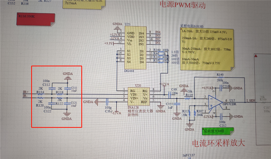
Schematic diagram
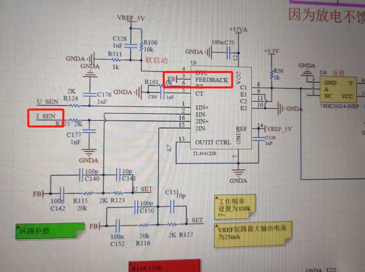
As shown in the figure above, INA128 is used for the output constant current loop sampling of the power supply;

INA128 differential output with RC low-pass filtering, as shown in the figure above, the loop appears obvious oscillation, and the FB waveform of the power chip is shown in the figure below:
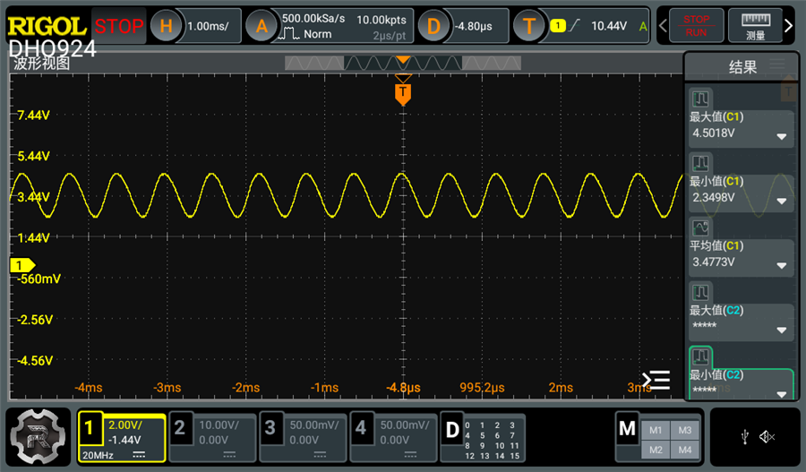
INA128输出如下:

The INA128 output is as follows:
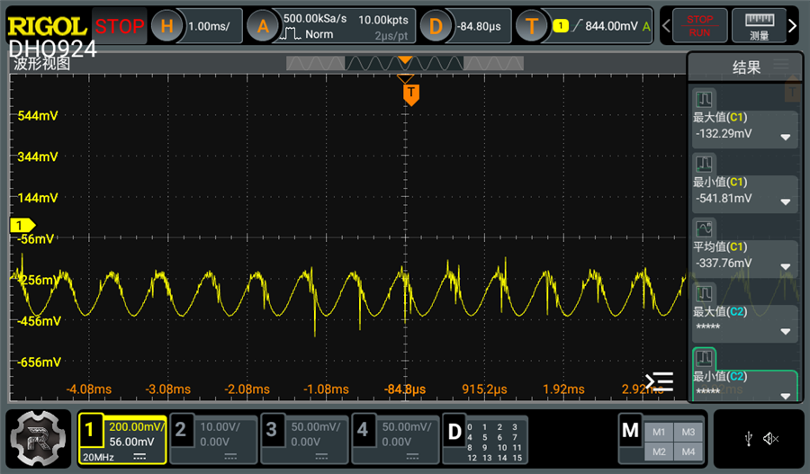
去掉差分输入的电容,电源芯片FB波形如下,波形比较稳定:

Remove the capacitance of the differential input, and the FB waveform of the power chip is as follows, and the waveform is relatively stable:
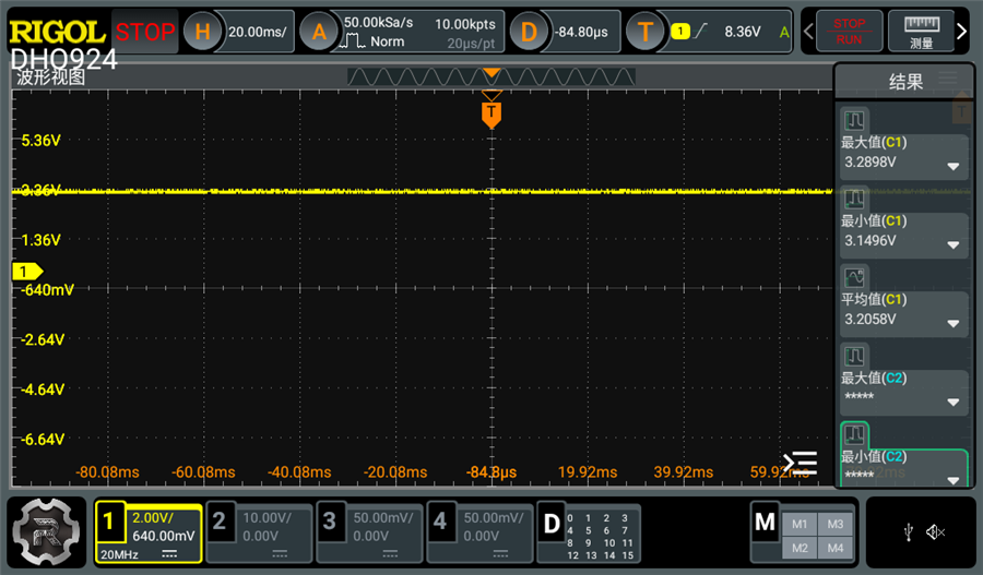
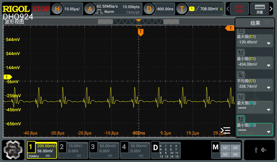
INA128输出,有比较大的开关噪声:

INA128 output, with relatively large switching noise:
  • Hi Albert,

    Capacitance at the input should not cause the INA128 to oscillate.  The input does not have any requirements for stability, the device only has a high input impedance and the output will track the voltages at the input according to the fixed gain. While the capacitance at the input shouldn't impact stability, the capacitance at the output certainly can, I see you have 1000 pF at the output but for this device this should still be OK.

    Is this INA being used in the loop of a larger system?  You mentioned that it is being used as "output constant current loop sampling of the power supply".  If this current information is being used within a control loop of a power supply, then I could certainly see how adding additional capacitance, and therefore delay and phase shift, can cause the system to oscillate.  I can't tell from the schematic above if the PWM device (TL494) outputs somehow connect back into the INA128 "IR+/IR-" nodes, but that seems to be the intention of the design.

    If you can "break the loop" by removing the feedback, is the INA still stable with the input capacitance?  Is it possible to connect the "IR+/IR-" nodes to GND, and verify that the device is stable?

    Regards,
    Mike