- Ask a related questionWhat is a related question?A related question is a question created from another question. When the related question is created, it will be automatically linked to the original question.
This thread has been locked.
If you have a related question, please click the "Ask a related question" button in the top right corner. The newly created question will be automatically linked to this question.
Tool/software:
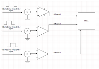
I would like to compare the rising edges of single-ended signals coming from three different sources. The signals have a frequency of around 100 MHz. I want to compare the data from these sources using an FPGA. Since the FPGA and SMA connectors will be physically distant from each other on the PCB, I am planing to convert the signals to differential on the PCB and route them that way. Below, you can see the block diagram.

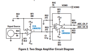
While researching this topic, I came across TI's High Performance Analog Front Ends app note.

However, I have a few questions, and I would greatly appreciate your help with them:
Hello MCAV,
I am supporting this thread for you. In terms of high speed single to differential conversion, your starting circuit is good. I will also research and provide support on other circuit implementations as well.
If the circuits do not need to be in a high gain, I can recommend some lower bandwidth FDAs as well.
Please confirm your bandwidth and gain settings, as well as available power rails.
Best,
Alec
For the single-ended signals applied at the input, we can consider the parameters as follows: Vhigh=2V, Vlow=0V, Frequency range= 50MHz-100MHz. For the differential output signal, we can consider the voltage values as follows: VCM=1.8V, Vhigh=VCM+350mV, Vlow=VCM-350mV. What I would like to ask you is this: I can convert SE signals to LVDS and feed them to the FPGA. For this, I can use the DS90LV011A. The propagation delay of this component changes with temperature. This may cause timing errors in capturing the rising edges of the signals. If we use an op-amp to convert to a differential signal, what will the propagation delay be? There is no information about the propagation delay of op-amps in the datasheet
Hello MCAV,
I would recommend simulating the LMH6703 to determine a metric for delay. With op-amps propagation delay is really the phase-shift, which has dependency on your gain and operating frequency. A transient simulation using PSPICE or TINA-TI with your parameters would be the most effective way to determine what you are asking.
You can implement filtering to reduce noise, depending on the dominant noise sources you are concerned about. Do not use overly large feedback resistors (which add resistor noise) and utilize good high speed PCB layout best practices.
Best,
Alec