This thread has been locked.

If you have a related question, please click the "Ask a related question" button in the top right corner. The newly created question will be automatically linked to this question.

OPA171: OPA171

Part Number: OPA171
Other Parts Discussed in Thread: TLV9301, OPA202, LM5575,

Tool/software:

Hello TI Team, 


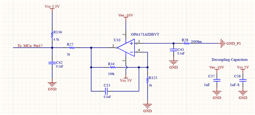
we are currently measuring a small signal with OPA171AIDBVT. Below the schematic.

We wanted to have more alternative options so we added two new more part numbers:

TLV9301
OPA202


Additional we have two types of waveforms in the design for the Vcc=5V. The 5V supply is generating from LM5575. 

The first one creates no issues to the output measurement.


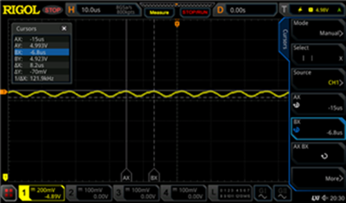
But there is an issue with the second waveform. 

By changing the input voltage of the LM5575 (from 15V to 60V) the maximum voltage of the spike is increased about 250mV at full range and the frequency of these spikes from 119kHz to 46kHz at full voltage range.

Now there is a change in the output voltage of the op-amp when changing the input voltage from 15V to 60V and this causes problems to some measurements.

This disturbance is only visible at OPA202. (ΔVos ~ 145mV from 15V to 60V change)

The other two op-amps are very immune to these changes. 

OPA171 (ΔVos ~ 3mV from 15V to 60V change)

TLV9301 (ΔVos ~ 145mV from 15V to 60V change)


What parameter of the op-amp datasheet should we consider in order to have an alternative that will not create any issues?


Regards,

KT

  • Hello KT,

    The attached schematic is illegible, please try again. It looks like the op amp measures the difference in ground nodes which are probably separated by a sense resistor. So it measure sense resistor current, voltage.  Which op amp does that best? It is not clear at all how the measurement connects to LM5575 and how that affects final 5V output. 

  • Hello Ron,

    Thank you for your answer. Please check again the attached schematic. Yes, this is exactly what the circuit does. But how you are going to check which op-amp can be used?

    The LM5575 supplies the Vcc 5V to the op amp V+ pin. You will be able to understand that better with the clear schematic. I checked the PSRR of the 3 op-amps but I couldn't find any connection with this value and the results.

    Thank you,

    KT

  • KT,

    OPA202 claims high capacitive load drive. Other than that long shot, I have no other initial advice. 

    The circuit values are a bit odd. pin 3 has 8 kHz low pass. Pin 2 feedback is 16 Hz. GND through feedback 1.6 kHz. Can you get waveform input signal for "GND_P1" relative to "GND"?  I can't know what parameters matter until I know the input signal. 

    Are the previous waveforms relative to "GND"?

  • Hello Ron,

    This was on of the first things I tried to do, but the input signal is to small to measure it with oscilloscope. Yes, the previous waveforms are relative to GND. 

    Thanks, 
    Konstantinos

  • KT,

    I see the differences in 5V. What are the waveform differences on pin1?