This thread has been locked.

If you have a related question, please click the "Ask a related question" button in the top right corner. The newly created question will be automatically linked to this question.

TLV333: Low-Side Current Shunt Op-Amp Circuit to Single-Ended ADC for Cost-Optimized Monitor Software Problem

Part Number: TLV333
Other Parts Discussed in Thread: TLA2024,

Tool/software:

Hello Dear All,

My circuit is exactly same with;
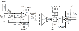
Just my voltage is different.

 I applied FSR value 0.512V as shown ;

Here my "Value hex" values is came from TLA2024 to my MCU; "Multimeter" values is the Amper of output.
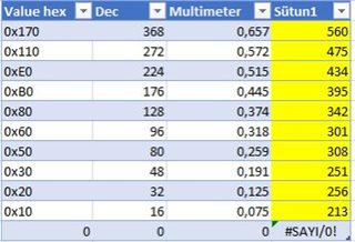
 

When I apply load at 10% intervals, I cannot establish a connection between the values ​​I measure with the multi meter and the HEX values ​​I get from TLA2024.

What can I have to do here for my Value Hex? How I figure it out the values to mean values?

  • Hi Sucu,

    Did you validate that the input analog signal has the following behavior?

    Difference Amplifier Isense 09172024.TSC

    What can I have to do here for my Value Hex? How I figure it out the values to mean values?

    The current Isens range per your circuit is up to 10.7A range. You mentioned that you applied 10% of load, let us say 1A, the meter should read approx. 0.46V at the output. 

    If your ADC's FSR is +/-0.512V, your ADC should be close to full binary code: 0.46V/0.512*2048 = 1840 counts. Full FSR counts should be 2048. 

    I am not sure what FSR you have configured at ADC based on the capture data - 0.657V/368 counts = 1.785mV/count (and you said that you have +/-0.25mV/count). 

    This is your 12bit ADC FSR range setting, which is +/-0.25mV/count. 

    Other consideration are: 

    1. Errors from 1mΩ shunt.

    2. Vos from TLV333 and ADC offset and gain errors. 

    Perhaps you would need to perform current calibration first per the circuit. If you have other questions, please let us know. 

    BTW, for ADC issues, you would need to submit a different query for it. We are supporting analog part of the circuit. 

    Best,

    Raymond 

  • Hello Dear Raymond,

    Thank you for you reply, and good answering. Yes I can see the behavior like that.

    Okay we can contiune with 1A and, 0.46V output. When my FSR İS +/-0,512V, what I have to do with 1840 and what is full FSR counts 2048, what is the value? and I dont get it what I have to do with 1840.

    When you are calcultaing adc based on capture data as I told you before my Multimeter values for Amper not for Voltage but I will measure the voltages and share with you.

    And we got values like;

    with that values, Can I find the load Amper? or just Ishunt?

    Regards

  • Hi Sucu,

    I will leave the query for the DCC-PADC support team, since I am only supporting analog related issues.

    Best,

    Raymond 

  • Hi Sucu,

    Is the question how to interpret the Hex values you are receiving from the ADC?

    At a Full-scale range configuration of ±0.512V, 1 LSB = 0.25mV.

    That means that for an ADC reading of '0x21E' Hex for example, decimal value = 542, so the voltage reading = (0.25mV * 542) = +0.188V

    This voltage measured across the shunt resistor can then be correlated to the current across the shunt using Ohms Law.

    I believe the issue is that you are treating the HEX output values as if this was a 16-bit converter.

    The TLA2024 is a 12-bit ADC, so the last 4 bits in the conversion register are reserved and always read as zeroes. These should not be used as part of your HEX value when doing the conversion to a voltage value:

    This means that the Highest possible hex value is = 0x7FF (because values are represented in binary two's complement), which in decimal = 2047 (However the full reading you would get from the ADC is 0x7FF0 since the register is 16-bits, but only the first 12 are relevant).

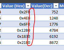
    The value should never be higher than 2047 when converted to decimal (since 2^11 - 1 = 2047) , but some of your values show higher than that, for example '0x21E0 = 8672' which would be incorrect.

    I believe that the problem here is that you are using the last four bits of the HEX ADC when you convert back to voltage values, which would make your values incorrect:

    Discard the last four bits (the '0' at the end of every HEX value), and your results might make more sense. 

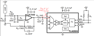
    All the ADC is doing, is measuring the voltage at the actual input pin, 

    Have you tried measuring the voltage seen at the actual input pin of the ADC? 

    Best Regards,

    Angel