This thread has been locked.
If you have a related question, please click the "Ask a related question" button in the top right corner. The newly created question will be automatically linked to this question.
Tool/software:
Hello Team,
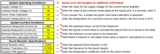
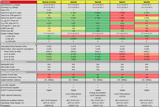
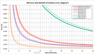
I was calculating current measurement error using your Current_Sense_Amplifier_Comparison_and_Error_Tool and got the below results.
However, I have few queries as follows:
1. Is ENOB value considered in the tool to calculate error in lower range ?
2. What output sample period is considered during the ADCRANGE & ENOB selection if applicable ?
3. Why there is no change in error value if I use INA236 full scale ADCRANGE 1 (±20.48-mV) or ADCRANGE 0 (±81.92-mV). Both selection showing same error under same condition.
4. Why aren't INA238 & INA228 having option to select different ADCRANGE ? Are the results same ?
4. Is external common-mode filter will reduce the error or was it considered to calculate Ibias ?
Regards,
Tamal Samanta
Hardware Engineering Team Lead
OÜ Skeleton Technologies
8th Floor, Alma Tomingas house, Sepise 7
11415 Tallinn, Estonia
Tamal,
Thanks for using the TI E2E and for using our devices and tools. Here is my responses to each of your questions:
1) No, the comparison tool does not take into account ENOB. As described in the equation, this is essentially using the "analog" equivalent specifications (offset, gain error, CCCMRR, PSRR, and the associated temperature drifts) to describe a first pass error and it is not intended as an in-depth worst case error tool. The primary scope as shown on the HELP tab is to enable an easy way to compare up to 5 of our current sense devices under user-defined system operating parameters.
2) This is fundamentally a DC error tool, so sample time, averaging, ENOB are not considered. You can think of this as all settings are to enable maximum DC accuracy.
3) Because the key DC performance parameters do not change with ADC range, unless the shunt value changes, there will ne no difference in the error calculation. I enabled the "Use maximum Calculated Shunt" field, and the errors now change as the ideal shunt values are 4x relative to each other:
4) We removed this from the tool since to truly understand the impact means you need to use the "Use Maximum Shunt Value" field and most users already have ad defined shunt they want to utilize.
5) No external filter effects are included, just simply the I-BIAS versus I-IN impact as shown in the equation. Since different devices have very different I-BIAS characteristics, we are simply doing the first pass effect at low currents of the TYPICAL I-BIAS.
Thanks, Dan Harmon
Product Marketing Engineer
Hello,
Thank you for answer. Let me ask a few more questions regarding same amplifiers:
1. What sigma delta modulator structure is used in the ADCs of these amplifiers? Mainly we interested in modulator order, but other details will be highly appreciated as well.
2. What is decimation ratio of sigma delta ADC? Do I understand it correct that decimation can be calculated from (1/(conversion time)) divided by sampling frequency? If no, could you please provide correct procedure or values.
3. What are the output lowpass digital filter parameters ? Is the time constant of the filter = conversion time? What is the filter order?
We need this information to create proper simulation model of the ADCs, to evaluate overall measurement accuracy of our main model, which will use measurements from INA chips as an input.
Best Regards,
Tamal Samanta
Hardware Engineering Team Lead
OÜ Skeleton Technologies
8th Floor, Alma Tomingas house, Sepise 7
11415 Tallinn, Estonia
Hello Tamal,
Here are my responses to your questions:
1. We do not actually give out details of the ADC structure, just what is in the datasheet. You may be interested in looking at sections 7.3.2, 7.3.4, and 8.1.3.
2. Section 7.3.4.1 of the datasheet does say that the digital filter performs both decimation and filtering, but does not give additional details about it.
3. The available information for the digital filter is in section 7.3.4.1 of the datasheet.
I realize most of these are not the answers you were hoping for. For this device, the affective measurement accuracy comes from the ENOB table (section 8.1.3). You can find the effective noise free voltage measurement for your specific settings using the ENOB table and this equation:
Noise_Free_Resolution = ADCRAGNE/(2^(ENOB-1))
Regards,
Mitch