Because of the Thanksgiving holiday in the U.S., TI E2E™ design support forum responses may be delayed from November 25 through December 2. Thank you for your patience.

OPA322: Pspice model giving errors for trise

Part Number: OPA322
Other Parts Discussed in Thread: TINA-TI, OPA2994,

Tool/software:

Hello 

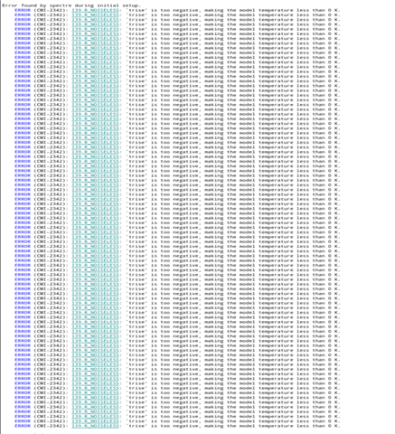
The Pspice model for opa 322 is actually giving. errors in Spectre claiming that T rise is too negative, which actually is make. the temperature go below zero Kelvin. Please suggest changes to the piece by scores and upload it to the product website.
  • Hello Usa,

    In the netlist for the model there is a device called R_NOISELESS. Set T_ABS to a different value, this may resolve the issue. Unfortunately we only support simulation in PSpice for TI and TINA-TI. Therefore, these models are tested to work in these two specified simulators, and we are unable to provide coverage across all possible simulators.

    Best,
    Jerry

  • Can I convert the .OLB files of Pspice to TI to TINA spice to pspice codes somehow or its not possible?
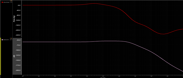
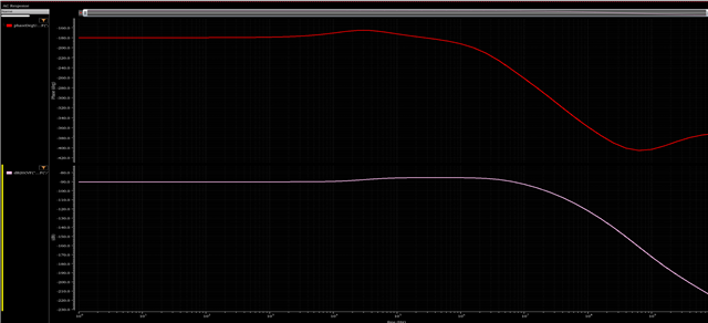
    By the way your solution didnt help much, it gives an incorrect AC response with negative scale (I see this error in another general purpose OPAMP OPA2994):

    OPA322 Response:


    OPA2994 Response:


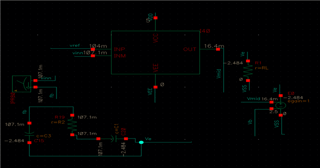
    For the below circuit:

  • Hello Usa,

    Unfortunately there is not a good way to convert between SPICE simulators. It also looks like you do not have a DC return path. Your output signal has a negative gain, which means it is attenuating the output. It also seems that your output value is railed to the negative voltage rail.

    When simulating integrator circuits, it is important to create a realistic capacitor, and place a parasitic resistor in parallel with the capacitor, as the simulator will consider this a perfect DC open circuit at low frequency. Adding a 1TH inductor in feedback will also help with this.

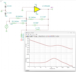
    Could you provide to me your component values? I have provided you a circuit with realistic capacitors below, but the values are not correct as they are not present in your above screenshot.

    8664.Integrator.TSC

    Best,
    Jerry

  • Hi Jerry 
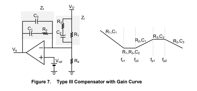
    So my target is to build this circuit as per TI document: "Demystifying Type II and Type III Compensators Using OpAmp and OTA for DC/DC Converters"
    (Here Vo is the Output of a buck converter and Ve is the error voltage output of the OPAMP used for PWM):

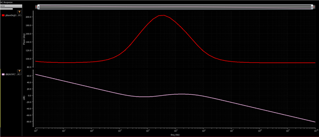
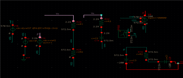
    When I use a VCVS ideal OPAMP I get the expected behavior for my calculated Rs and Cs:


    For below Circuit:

    As seen this is how my phase and gain plot should look like with the phase boosting and also gain plot as similar to TI reference document. Now I need any OPAMP (Pspice model) from the TI database that has a rail to rail Input/Output and a Unity Gain Frequency of at least 20 MHz. Plugging the OPAMP in figure 7 should give me some values across the Vo range but not saturating like you saw before hitting -ve rail. For now It either hits the negative rail or the positive rail (for other OPAMP models). 


    My Rs and Cs
    R1 = 30kohm
    R2 = 15kohm
    R3 = 12kohm
    R4 = 10kohm
    C1 = 3.3 nF
    C2 = 220 pF
    C3 = 22 pF

    PS: TINA-TI was having installation issues and I couldnt see the circuit you attached.

  • Hello Usa,

    Testing this circuit in TINA-TI seems to yield the expected results.

    I would try adding a 1TH inductor in feedback across the amplifier. This is a simulation workaround when a DC feedback path cannot be established with ideal components. Since it is such a large value, it will be effectively open for any AC circuit of any interest.

    Best,
    Jerry

  • Thankyou so much for the prompt reply Jerry, I appreciate you highly, I have two more important things to ask before you close this

    1. While I figure out the installation of TINA-TI, can you simulate to show the DC parameters of this configuration, can you reply back with what a common mode input of 500 mV and 2V yield (where you have connected the Vsource before the inverting input and the GND on the non inverting input)? Since before you saw the value of Ve (OPAMP output) hitting the rails.

    2. Can TINA-TI be used for doing a pre PCB simulation of PSPICE/TINA files to know the circuit behavior before making a PCB of those components?

  • Hey Usa,

    At DC, this configuration will simply drive the inputs equal to each other. The analysis was done with split supply and a CM of 0V to facilitate easy biasing, and shifting the supply and common-mode voltages will not change the simulation output for AC analysis. There are small effects based on the magnitude of the supply voltage that are not modeled, but these will not greatly impact the function of your circuit.

    TINA-TI c an be used for pre-PCB simulation, however, your simulation is only as good as the amount of variables that you know. Any simulator will make some ideal approximations to ease calculation time. Knowing where the ideal differs from the real is what makes your simulation valuable.

    Best,
    Jerry

  • Thanks Lastly I understand that the inputs will be driven equal to each other at DC, But what about the output? Will it be different for different common modes or like you say that it will hit the rails as in my cadence Pspice simulation? 

  • Usa,

    An integrator circuit has "infinite" gain at low frequency, so in a DC simulation, it will show the output to be railed based on which input is being driven higher. Since there is not a DC current return path on the amplifier, it is relying on the switching regulator control to drive the inputs equal to each other. This simulation is not complete as a DC simulation without the corresponding other feedback components.

    Best,
    Jerry