Other Parts Discussed in Thread: PGA870
Tool/software:
Hello,
TI provided me MATLAB code for the PGA870EVM attenuator, which is used to adjust the attenuation level of the attenuator in MATLAB. I was able to get this code working on my laptop, so I am able to adjust the attenuation level in 5 dB steps within an accuracy of 0-0.3 dB.
However, I noticed that the actual attenuation level measured on the Spectrum Analyzer seems to be 10 dB lower than what I set it to using the set_gain function from the PGA class. I’m wondering if there is an explanation for why this could be happening.
For example, I injected a -5 dBm signal at the input of the attenuator, and had the output port directly connected to the Spectrum Analyzer. Before I call the set_gain function for the first time, the signal on the spectrum analyzer has a measured power of -5.55 dBm. But when I create the PGA MATLAB class and call myPGA.set_gain(0), the output power drops to -16.7 dBm. I would have expected the measured power to stay at roughly -5.55 dBm to reflect an attenuation of 0 dB.
Similarly, when I call myPGA.set_gain(-20), the output power drops to -36.8 dBm. I would have expected it to be -26.7 dBm.
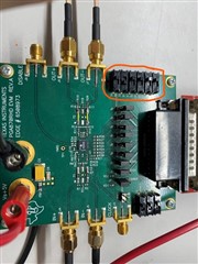
I am using single-ended input and output connections. So I am only injecting RF signals into the IN+ port of the attenuator, and nothing is connected to the IN- port. Similary, the Spectrum Analyzer is only connected to the Out+ port; nothing is connected to the Out- port. Also, my DC power supply is supplying 5 Volts to the Vs port.
Is there an explanation for why I am observing this 10-11 dB degradation in attenuation level from what I set in the MATLAB code?


