This thread has been locked.

If you have a related question, please click the "Ask a related question" button in the top right corner. The newly created question will be automatically linked to this question.

OPA328: Regarding use of OPA328 in SAR reference buffer circuit.

Part Number: OPA328
Other Parts Discussed in Thread: TIDA-01055, REF35, OPA388

Tool/software:

Hello TI support,

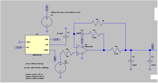
We are going to use OPA328 for SAR reference buffer circuit. I gone through TI design, TIDA-01055 and document "Do-it-yourself: Three Ways to Stabilize Op Amp Capacitive Loads". I have attached the image of the circuit & below are some explanations,

1. I have used RISO+DFB+RFx as compensation method for 20uF output capacitor. The circuit is stable but closed BW is near 7.4KHz (-3dB). 

2. SAR is designed to work on approx 2MSPS. So is it acceptable that reference buffer circuit with near 7.4KHz BW is sufficient for this application? provided reference may see transient at much higher frequency.

3. How wideband amplifier will play the role for such application with above mentioned BW.

Regards,

jagdish

  • Sorry,

    I missed below information.

    We are going to use REF35 series with 2.5V reference & the converter is 16-bit with target ENOB of 15-bit. Please advise ahead.

    Regards,

    jagdish

  • Jagdish,

    What is the maximum frequency that should reach output? Why is the 20uF load there? 

    How wideband amplifier will play the role for such application with above mentioned BW.

    Faster op amps will result in circuit being more defined by passive component selection (extra gain used to lower distortion and phase shift). Slower ones will have more variance from an ideal op amp. 

  • Hello Ron,

    1. The output 20uF ( is tunable as per throughout & REF current requirements) is recommended capacitors by most designs to support transient current requirements when sampling speeds are 1Msps or greater. Please have look at TI's TIDA-01055.

    2. I believe, there will be burst of 16Msps on reference pin (to accommodate 16-bit decisions) to support 1Msps data conversion & hence I asked the question about low BW of closed loop compensated circuit. Your thoughts on this will be appreciated.

    3. The other question comes is if compensated circuit is to yield low BW then why do we use wideband amplifier? Can we take OPA388 which is having much better offset & drift specs?

    Awaiting your response.

    Regards,

    jagdish

  • The wideband buffer amplifier is needed in order to settle Vref transient spikes generated by ADS sample&hold to required precision (1/2 LSB of 16 bits) within converter’s each conversion cycle. For this reason, cut-off frequency, fc, of the reference buffer configuration is not what determines the settling time of the reference voltage. 

  • OK, You mean to say settling time works independent of cut-off frequency of ref drive circuit. If that's the case do you think there any limits of cut-off freq of buffer (for ex min should be 4K or so) for the ref buffer to work? Or it is completely independent?

  • A cut-off frequency is an AC parameter while settling time is a transient - they are related but not directly correlated. In short, you don’t need to concern yourself with the AC  bandwidth of the reference buffer.  All you need to do is to optimize the RC of the output so the Vref settles to required precision between ADS conversion cycles.