INA310A-Q1: INA310-Q1 application question

Part Number: INA310A-Q1

Tool/software:

Hi expert,

Have below INA310A1 application question, which need your help.

1. What is the maximum carrying capacity of OUT?

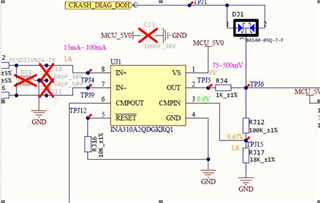
2. pls help review the sch as below
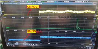
3. we found output not stable when the input as below, pls help analyze the potential reason,(the CMPOUT pulled up to 5V)
  • Hangjie, 

    Thanks for using E2E!

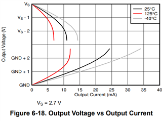
    1. The max current out of the device is going to be based on the design's need to swing as per figure 6-18 in the datasheet:

    The claw curve shows the maximum amount of current the part the device can deliver while maintaining the given voltage. I typically advise customers to provide a bit of margin away from the curve for best design practice, as you begin to see certain nonlinearity contributions as you approach the curve. This app note goes into detail on this topic if you would like to know more. 

    2. Would it be possible to screen shot more of the passive components attached to the schematic? I cannot see the input structure, or what the output is driving to provide feedback there. For the portion that I can see, I would recommend removing RJ16 from the RESET pin and tying this directly to GND for transparent mode operation. I would also recommend population of the bypass capacitor to the 5V line into the device, as recommended in section 8.3.1. It looks like the customer has designed this into the schematic, but then DNP'd the passive. 

    3. Again, would it be possible to see what CMPOUT is connected to here? Could they also capture their 5V waveform alongside the CMPOUT on the scope to ensure this is not potential ripple coupling off of the supply voltage?

  • Hi Carolus,

    Thanks for your quick reply.

    1. why our DS do not recommend the divider network lower than 100k? what affect if customer use 118k divider?

    2. For 3, since customer can not share the full sch, form my understand, it seems the CMPOUT abnormal when CMPIN near 0.6V, whether it related with internal ref is 0.6V and the VTHRESHOLD is 8mV? 

  • Hangjie,

    1. We recommend this summation for accuracy purposes. The input is high impedance, but not extremely high that large resistor values would potentially affect accuracy. A total of 118kΩ would most likely be fine, but would introduce slightly more error than a 100kΩ total. 

    2. I'm afraid I don't understand your question here. From the plot attached, the CMPOUT properly asserts high when CMPIN steps up, which I would expect, provided the threshold voltage has been crossed. The instability shown in the waveform does not look to be like activation of the CMPOUT pin in my opinion. Once the CMPOUT node pulls low, CMPIN would need to reduce by 8mV to reassert high, and this does not appear to happen. This looks more like noise that is propagating through the power supply, hence my request to see the supply on scope alongside the CMPOUT pin. Also, what is the green trace on the scope in the plot?