- Ask a related questionWhat is a related question?A related question is a question created from another question. When the related question is created, it will be automatically linked to the original question.
Tool/software:
Hi team,
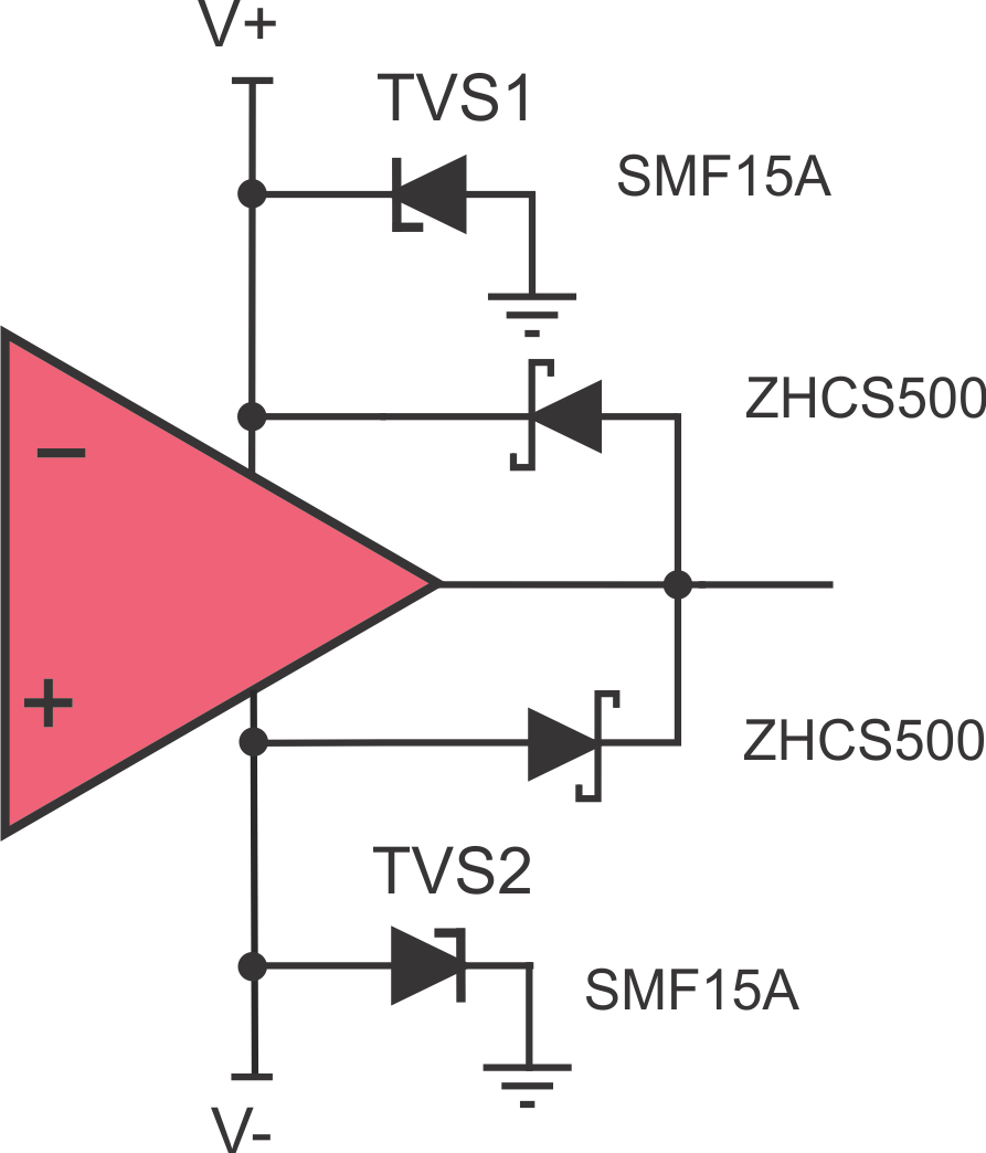
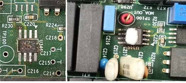
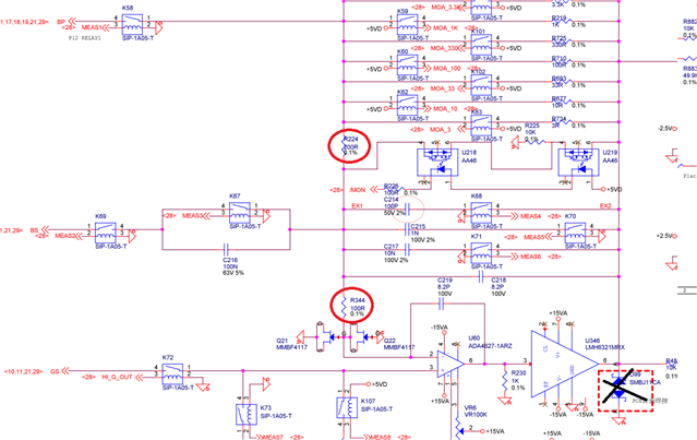
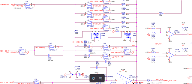
The customer has a broken issue here. Could you review the schematic and then give some suggestions here?
customer designed an LCR meter to use the below circuit as a detect parameter function. Thanks
a simple block
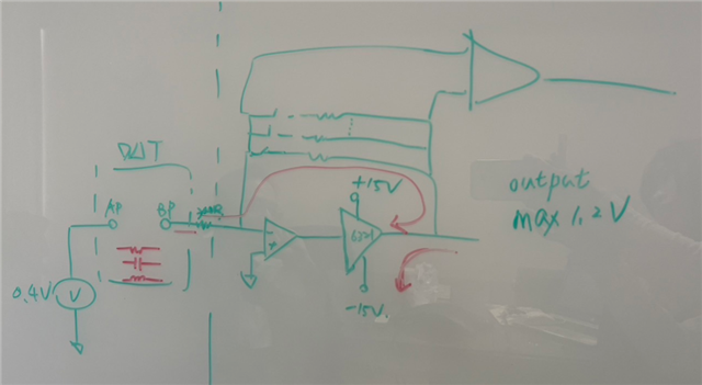


 (From this