This thread has been locked.

If you have a related question, please click the "Ask a related question" button in the top right corner. The newly created question will be automatically linked to this question.

XTR117: XTR117 (0-10V to 4-20mA)

Part Number: XTR117

Tool/software:

Hey, I want to use the XTR117 to convert a 0-10V signal to a 4-20mA signal.

On my board, I have an Analog Voltage Output that provides a 0-10V signal, and on the same board, I have an Analog Current Input circuit that reads a 4-20mA current in a two-wire 4-20mA current loop configuration.

I am designing a testing jig where I can loop the Analog Voltage Output port to the Analog Current Input port, for which I require a converter circuit that I can attach in between.

How should I connect these, and what should be the value of RIN?
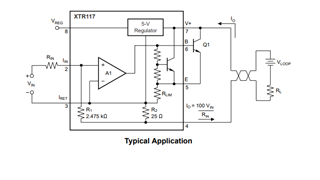
With Reference to this image. 

  • Also for Loop I will use 24VDC

  • For 0-10V to 0-20mA, I think it is straightforward with the attached image. RIN will be 50Ω. I will connect 24Vdc at V+ (Pin 7) and Pin 4 to my current reader circuit. IRET will be connected to the ground of the same board. Right? 
    How to make it 4-20mA. 

  • Hi Dheeraj,

    The math isn't hard but there's a few steps and design considerations to take into account. 

    First, it's important to remember the relationship between the output current and the input current. In the case of the XTR117 the relationship is as follows: 

    Second, because you are going from 0-10V input to a 4m-20mA output, you'll need an offset voltage for the 4mA. The example they give here is using the Vref of 2.5V which will generate the needed 40uA when you put a 62.5kohm resistor to the Iin pin. 

    So now we need to calculate the second resistor. We know that the input current will need to be a maximum of 160uA at a 10V input so we plug the values we know into V = I*R to get the second resistor to be 62.5kohms. 

    Third, as long as the signal that is generating the input signal shares the same local ground as the Iret pin then the circuit should work properly. Grounding is super important in 2 wire transmitters. You want to make sure Iret is not tied to the loop ground as that will cause issues. More information can be found in the 2-Wire 4-20 mA Sensor Transmitters: Understanding the 2-wire Transmitter GND (Part 2)

    Hope this helps!

    Best Regards,

    Robert Clifton 

  • Please correct me if I misunderstood it. Since the XTR117 Vreg is 5V, I am planning to use it to provide the 4mA current. This means the Rin value will be 1.25 kΩ, right?

    Also, for the arrow indicating the current (0 µA to 160 µA), I will connect my 0-10V signal there.

    Thank you for the quick reply!

  • Hi Dheeraj,

    You are correct. I wanted to match with the example given in the image but Vreg should be 5V! Sorry for the confusion.

    Since the XTR117 Vreg is 5V, I am planning to use it to provide the 4mA current. This means the Rin value will be 1.25 kΩ, right?

    Not quite. You are forgetting that you are wanting to generate an Iin = 40uA which will be amplified by 100 to give a Iout of 4mA. So you are wanting the Rin to be 125kohms. 

    I went ahead and modified the circuit to better reflect your needs. 

    Best Regards,

    Robert Clifton 

  • Thanks Robert 
    This is my final schematic. 

  • Hi Dheeraj,

    I'm concerned with the BC817k transistor. The amount of power that needs to be dissipated could be as high as 0.48W (P = V*I with V = 24V and I = 20mA). From what I read the BC817 might struggle depending on how many layers you have. I would recommend ensuring that this transistor will work in your system.

    Also, make sure that the I_RET's ground is truly a local ground and not connected to the main ground as we have discussed before. 

    Best Regards,

    Robert Clifton