

Part 1 of this blog series provided an overview of the operation and uses of 2-wire 4-20 mA field sensor transmitters and provided a basic example system. The post also introduced the current transmitter compliance voltage, which when violated prevents the transmitter from properly regulating the current loop.
Today we’ll discuss the circuitry that regulates the output current of a 2-wire transmitter by deriving the basic transfer function. Using the transfer function we will then explain another common application issue caused by connecting the transmitter return (IRET) to the loop supply ground (GND) or a fixed potential relative to the loop supply GND, as shown in Figure 1. The transmitter can’t regulate the output current (IO) if IRET is connected to GND or another potential. It’s a very common question with a fairly simple solution.
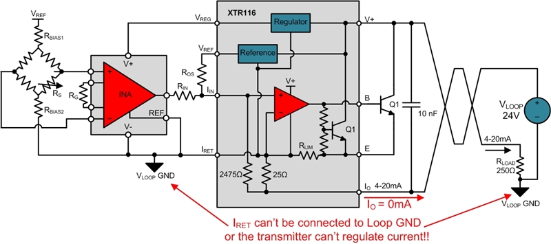
Figure 1: 2-wire transmitter with IRET incorrectly shorted to VLOOP GND
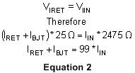
To understand why these issues occur, let’s use Figure 2 to take a closer look at the operation of the XTR116 with a focus on the IRET pin. As marked below, the XTR116 IRET pin serves as the local, or 2-wire transmitter GND, for the sensor excitation and conditioning circuitry. The output voltages of VREG and VREF are referenced to IRET. The circuitry they power, including the bridge, instrumentation amplifier (INA), and internal op amp (U1), all return current to the IRET pin as defined in Equation 1. The IRET currents are marked in blue in Figure 2.
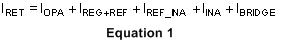

Figure 2: XTR116 4-20mA transmitter showing current flow
The IRET current sums with the bipolar transistor (BJT) current (IBJT), shown in orange, and flows through the 25 Ω sense resistor. The input current (IIN), shown in green, flows through the 2475 Ω sense resistor and then sums with IRET and IBJT to form the final 4-20 mA output current (IO), shown in red. The voltage drop across the 25 Ω resistor (VIRET) connects to the op amp inverting input and drop across the 2475 Ω resistor (VIIN) connects to the non-inverting input. Therefore, the op amp will regulate IBJT such that VIRET and VIIN equal. Equation 2 uses Ohm’s law to determine the ratio of the currents flowing through the two resistors.
Since IO equals the sum of IIN, IRET and IBJT, we can simplify Equation 2 as shown in Equation 3, which is the final transfer function.

We can now define the voltage at IRET relative to the VLOOP GND. Figure 3 shows that VIRET depends on the 25 Ω internal resistor, the 250 Ω load resistor (RLOAD) and IO.
Figure 3: Determining the VIRET voltage relative to VLOOP GND
VIRET is defined in Equation 4.
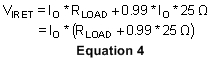
VIRET is based on IO and therefore will change as the output current changes. This is shown in Figure 4 by measuring the VIRET voltage over the 4-20 mA IO span.
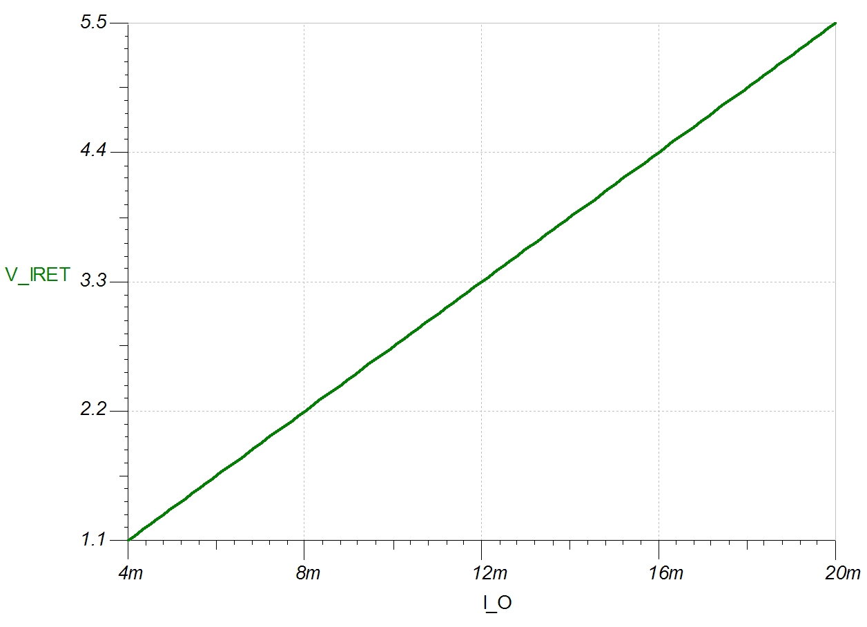
Figure 4: Measuring VIRET while sweeping IO
Connecting IRET to VLOOP GND, as shown in Figure 1, forces VIRET to 0 V. Therefore, the transmitter can’t regulate the output current because the VIRET voltage is not allowed to move up and down with the output current.
It is common to inadvertently connect IRET to VLOOP GND during testing or calibration/programming of the system. For example, making measurements with an oscilloscope on the transmitter side referenced to IRET, while making measurements on the loop side referenced to VLOOP GND, will short IRET and VLOOP GND together. This happens because the negative probe connections of the oscilloscope channels are internally connected, and also usually connected to earth GND.
The preferred solution is to reference all oscilloscope probes to VLOOP GND and use an additional oscilloscope channel to monitor the voltage at IRET. For measurements on the transmitter side, simply subtract the IRET voltage using the oscilloscope MATH function to obtain the measurement without shorting the IRET and VLOOP GND node.
In my next blog post we’ll talk about the current consumption limitations that affect the sensor and transmitter circuitry powered from VREG and VREF.
See more posts in our 2-wire transmitters series.
Related TI Designs for 2-wire transmitters:
- Bridge Sensor Signal Conditioner with Current Loop Output, EMC Protection
- Low Cost Loop-Powered 4-20mA Transmitter EMC/EMI Tested Reference Design
Related 3-wire blog posts from Kevin Duke:
- See an overview of analog outputs and architectures.
- Read about the evolution of 3-wire analog outputs.
