Tool/software:
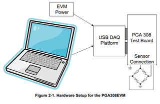
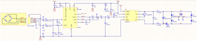
I'm using a PGA308/XTR116 to convert a strain gauge output into 4-20mA.
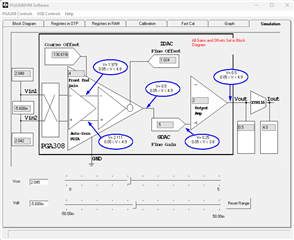
Measuring the bridge voltage directly and calculating my offsets and gains seems to work well to give me 0.5 and 4.5V on VOUT of the PGA308 and then the XTR116 to translate that to loop current.
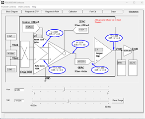
BUT, if I try to calibrate by measuring VOUT and back-calculate the bridge voltage (using the transfer function), it all goes haywire and my calculated offsets/gains sometimes cause the output to be shifted high or low and more often than not - saturated at 0 or 4.7V volts.
This could be because we are using such a tiny range of the strain gauge. Vs is 4.096V, the high-low delta across the bridge varies about +/- 4 to 7mV depending on the product configuration. Gains are typically in the 2000-3000 range.
I'm now looking at options to directly measure the bridge voltage to do the initial offset/gain calculations, then measure VOUT to do the fine tuning on ZDAC and GDAC.
I stumbled across the ADS1232. Would that be a good choice to measure the bridge voltages directly? The big package is a bit troublesome, but I may be able to make it fit.
Looking for recommendations for a good ADC to measure each leg of the bridge without causing any problems with the PGA308. Any advice from you gurus?
Hello Ky,
Thank you for posting on e2e. I am working on this thread and working through the calculations on my end regarding the PGA308. Will transfer the thread responsibility to the ADC team once finished.
All the best,
Carolina
Hello Ky,
I am having a hard time visualizing the connection, is it similar to this provided in the user's guide?
If not, what do you mean by connecting to each leg? Is there a schematic or block diagram you could share? Are you using the EVM?
This could be because we are using such a tiny range of the strain gauge. Vs is 4.096V, the high-low delta across the bridge varies about +/- 4 to 7mV depending on the product configuration. Gains are typically in the 2000-3000 range.
I think the PGA308 can handle this, what is the resistance of the strain gauge? Do you have a datasheet?
If the output of the PGA308 is 0 to 4.7V, it sounds like the output is being saturated. Since the bridge is connected to Vs 4.096, but the PGA308 is outputting 4.7V, does that mean the VExcitation ≠ VsupplyPGA?
All the best,
Carolina
Not sure if that is readable - but it's pretty much verbatim from the EVM user's manual. I'm using an ADC and/or Fluke meter to sample VFB and a microcontroller to talk to the PGA308. The strain gauge is 5K. I have 4.096V connected to the bridge excitation voltage and to VREF on the PGA308. I have the 5V supply from the XTR116 connected to VS and VCLAMP of the PGA308. (I misspoke in the original post).
If I use a Fluke meter to measure VFB and then back calculate the bridge voltage using the PGA308 default settings, then the calculated offsets and gains tend to saturate the PGA308. It works on some PGA308s better than other, but more often than not causes the PGA308 to saturate. However,
If I use a Fluke to measure the bridge voltage and then use those to calculate offsets and gains - it works as expected.
I'm certain the PGA308 can handle this, but the method of measuring VFB and using the transfer function to determine bridge voltage just isn't working well enough for me. Is that expected?
Hello Ky,
Interesting, first thought is that the fluke meter is providing an impedance path and therefore accidentally loading Vfb in an unexpected way.
Vfb is used for an accurate dc feedback path for the device to self-correct. Since the fluke meter is connected in this section, it is trying to "fix" something that isn't really there and therefore the amplifier over-corrects and rails.
The only difference I see between your schematic and the EVM is that you do not have a CL & RL at the VFB, the CL is implemented to filter EMI/RFI.
I'm going to try in lab to see if I get the same result.
All the best,
Carolina
As far as loading goes, I'm using an LCM7101 op-amp as a unity gain follower to isolate my ADC from vfb. I too worried about loading, so here's what I did to see if that could be the problem.
I removed the op-amp to open up that portion of the circuit and the measurement from the fluke didn't change.
With the op-amp/adc in place, I get the same measurements from the ADC with, and without the fluke.
The measurements on the ADC and the fluke are the same. So I don't think there's any loading of VFB happening.
I did add the filter to one board as a test and it didtn't change anything either.
Hello Ky,
Very fast reply! Can you show me your 1W circuitry?
All the best,
Carolina
No problem. I'm using an open drain buffer to combine the RX/TX pins on a usart. (the chip on the left is the micro-controller). I haven't had any issues at all with communications.
Hello Ky,
Thank you for providing the 1W circuitry, I don't see anything that can be the problem.
I will test it in lab when I am back in the office on Tuesday, Monday is a US Holiday.
In the meantime, do you have access to the TI EVM? If so, could you connect to the sensor and the fluke meter on Vfb and see if it replicates?
Can you also tell me how you are setting the internal gains? Are you using the PGA308 software?
What are the gains that have been selected for front end gain, coarse offset gain, and output gain? The device prefers to have the gains evenly spread across.
All the best,
Carolina
I am not using the EVM. I'm using my own board that has the above schematic.
I am setting internal gains through the one-wire communication - writing the registers directly using a microcontroller.
On power-up, I write the following registers:
SFTC = 0x0050 (1-bit delay during one-wire reads, run from RAM)
CFG2 = 0x0800 (enable VOUT, instantly)
CFG1 = 0x0000 (factory default)
CFG0 = 0x0000 (factory default, input gain = 4.0, output gain = 2.0, coarse offset = 0)
GDAC = 0x4000 (factory default) gdac = 0.5
ZDAC = 0x4000 (factory default) Vzdac = +1.024V (vref = 4.096V)
Then, I measure the bridge voltage (VBR = VIN1 - VIN2) and VFB at min and max conditions:
VBR_min = -0.0056V, VFB_min = 0.996V
VBR_max = -0.0041V, VFB_max = 1.002V
My target VOUT min/max is 0.5V and 4.5V.
I would like to note here that using the transfer function from 3.1.1 in the User's guide, the calculated Vout (VFB) should be (1.0016V and 1.0076V), but I'm actually measuring 0.996V and 1.002V telling me there is some sort of offset that the transfer function isn't accounting for. This offset seems to vary from chip to chip. I've tried ten different boards using the same strain gauge and same min/max conditions. The measured VBR is very consistent from setup to setup. The measured VOUT delta is very consistent from setup to setup (right at 0.006V), but the actual values of VOUT_min vary from 0.992 to 1.004.
If I use the measured VBR, I come up with a needed gain of 2666.667 (4.5V-0.5V)/(-0.0041V-(-0.0056V)). Using table 3-2 in the user's guide, I come up with input gain of 1200, output gain of 3.6, and calculate GDAC to be 0.617284.
I set the coarse offset close to the negative of VBR_MIN (0.00512) and come up with:
CFG0 = 6E05
GDAC = 6D09
ZDAC = 4DF0
Writing those values to the PGA results in a new measured VFB min/max of 0.279V and 4.235. That's not too far off from the needed 0.5V and 4.5V, but isn't quite there yet.
All the above is using measure bridge voltage values which I don't currently have a means to do within the circuit. From what I've read, I should be able to measure VOUT and use the transfer function to calculate the bridge voltage ( I do have a means to measure VOUT from within my circuit).
Doing it this second way, I measured 0.996V and 1.002V - giving me calculated Vbr of -0.0070V and -0.0055V.
needed gain is still 2666.667. Using table 3.1 still gives me an input gain of 1200 and output gain of 3.6 and calculated GDAC to be 0.617284.
The coarse offset is now 0.006144 giving me:
CFG0 = 6E06
GDAC = 6D09
ZDAC = 31BD
Writing those values to the PGA results in a new measured VFB min/max of 4.097V and 4.734V. The alarm register is still 0x00.
Am I doing something wrong in my lookups/calculations?
If not, then I'm not seeing great accuracy in the transfer function - meaning I probably will not be able to use VOUT to back-calculate VBR. Is there a way to account for this offset? or should I just focus on measuring the actual bridge voltage?
Then, I measure the bridge voltage (VBR = VIN1 - VIN2) and VFB at min and max conditions:
VBR_min = -0.0056V, VFB_min = 0.996V
VBR_max = -0.0041V, VFB_max = 1.002V
Hello Ky,
The VBR should not be negative number and is defined backwards to how you are currently measuring.
VBR = VIN2 - VIN1 (TP4 - TP2)
If you are still seeing a negative number with this definition than I recommend implementing the input mux for sensor output polarity reversal and a coarse offset adjust, see Figure 3-5 as an example.
Once that has been implemented, could you tell me the value at TP4 and TP2? I would expect them to be around 2.048 (~±5mV).
All the best,
Carolina
In the desired 0.5V/4mA position, with all default PGA308 gain/offset values with the exception of the mux bit.... I'm measuring 2.0444V at VIN2/TP4 of the PGA308 and 2.0500 at VIN1/TP2. I measure 0.985 at VFB.
In the other position (desired 4.5V/20mA), I get 2.0451 (VIN2/TP2), and 2.0492V (VIN1/TP4) with 0.994 at VFB.
Can you walk me through the offset/gain settings? I've been through the user guide several times and have triple-checked my math - but must still be doing something wrong.
Hello Ky,
Thanks for patience as I worked my way through this.
Even if you do not use the TI EVM, I recommend you use the software available on the product page, it will calculate the needed offset and gain settings needed. The simulation tab in the program has sliders for both VCM and VDIFF, the gain and offsets are chosen in the Block Diagram block. It will calculate out what is needed to get the required Vout/Iout:
0.5V/4mA position, with all default PGA308 gain/offset values with the exception of the mux bit.... I'm measuring 2.0444V at VIN2/TP4 of the PGA308 and 2.0500 at VIN1/TP2. I measure 0.985 at VFB.
For this outlined scenario, the Vdiff is 5.6mV and the VCM is 2.0472V.
The closest the program gets is 2.045V for VCM, VDIFF is -5.6mV. A coarse offset of -136.619mV gets precise 0.5V/4mA output. This will likely have to be shifted by a couple of mV considering VCM is not 2.045V and is actually 2.0472.
In the other position (desired 4.5V/20mA), I get 2.0451 (VIN2/TP2), and 2.0492V (VIN1/TP4) with 0.994 at VFB.
For the second outlined scenario, the Vdiff is 4.1mV and the VCM is 2.04715V. I am also assuming that TP4 is meant to be VIN2 not VIN1 (to match the min pressure scenario).
Similar to the minimum pressure, the closest the program gets is 2.045V for VCM, VDIFF is -4.1mV. A coarse offset of 1.025mV with input gain of 400, ZDAC of 1.024, GDAC of 0.617279, and output gain of 2.4 yields 4.554 and 20.216mA. I would play around with these numbers a little bit considering its not the precise VCM and the 4.5V/20mA needs a little work.
What is really nice about the EVM and software is that it will auto-cal for you so you only have to put the sensor's offset (V/V) and Span (V/V), the desired output, and power supplies and the program will calibrate the device to reliably produce the same output each time.
Most of the engineers buy the EVM, auto-cal it once with each sensor and populate the already calibrated device with the sensor in the end-equipment.
All the best,
Carolina
I've purchased an EVM board and went through the calibration with decent results.
measured inputs are 4.326mV and 5.795mV
Ram is ZDAC: 0x834, GDAC: 0x72E, CFG0: 0x6E84, CFG2: 0x1800
Output is: 0.4954 and 4.5804
These gains are consistent with what I calculate using the procedures in sbou069b as i would expect.
If I understand the mux bit correctly, I can reverse the two bridge inputs which then measure as abt -4.3mV and -5.8mV, flip the mux bit in CFG0 and get the same results -however that is not what I'm seeing.
When I do that, I get:
measured inputs are -4.324mV and -5.793mV (seems reasonable)
The only thing I changed in RAM is CFG0: 0x6F84 (to change the MUX bit)
The output I now measure is 0.192V and 0.197V
What am I missing here?
Hi Ky,
I will help to answer while Carolina is OOO. I believe what is happening is that in order to change the MUX bit, you need to set the register to 0x7E84. Please see the "Help with Current Reg" pop-up window in the software, under the Registers in Ram tab.
What you have set currently with the 0x6F84, is changing the Front End PGA gain from 1600 to 1200.
Please let me know if this changes your output measurements.
Thank you!
Regards,
Ashley
Thank you Ashley. I knew better and still goofed that up. I appreciate your attention to detail. I do get 0.5 and 4.5 as expected when I reverse the leads and (correctly) flip the mux bit.